![]()
![]()
![]()
![]()

![]()
![]()
![]()
![]()
![]()
![]()
![]()
![]()
![]()
![]()
![]()
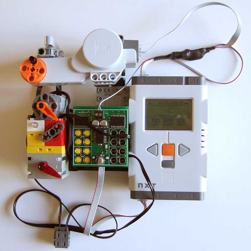
Deriving
power from NXT® motor port A
While reading datasheets of motor drivers chips inside NXT,
I discovered something interesting: the Sanyo LB1930M
that drives motor port A has a behavior different from LB1836M
that is used for ports B and C. Once the motor A is either running
or in brake mode, one of the two motor driving lines is at battery
voltage (for ports B and C, both lines are at ground voltage
while in brake mode). This behavior is summarized in the truth
table below, adapted from datasheets:
Mode |
Driver In1 |
Driver In2 |
Driver
Out1 |
Driver
Out2 |
Driver
Out1 |
Driver
Out2 |
Forward |
H |
L |
H |
L |
H |
L |
Reverse |
L |
H |
L |
H |
L |
H |
Brake |
H |
H |
H |
H |
L |
L |
Coast |
L |
L |
Off |
Off |
Off |
Off |
So if we combine with diodes the two drivers output
available on pins 1 and 2 of motor port A, we have a permanent
supply which can be used while motor A is operated in all modes
except coast. We are even able to switch off this supply by
setting motor A in coast mode.
Warning: this cable works properly only on motor port A!
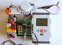
This supply can be used to provide power to external devices while keeping all NXT motor ports, and without adding a big and heavy battery box. I successfully used this trick to power an external wireless camera, or to supply a Mindsensors motor multiplexer.
Of course the motor driver has some limitations, you can expect to have a maximum permanent 800mA current to be shared between motor A and the external power. This is enough nonetheless to power a NXT motor and four 71427 motors behind a motor multiplexer, all medium loaded.
May 2007 update: PTP came up with another external power scheme, see it on NXTasy forum.
Supply cable building
- High resolution (Divx5, 2.6Mb)
- Lower quality/resolution (Divx5, 420kb)
Here is the schematics of the power derivation cable. All wires go straight from one NXT plug to the other, so the cable can be used as a regular one to connect a NXT motor to NXT port A. Two diodes, D1 and D2, combine motor drivers output to provide permanent power. I choose 1A rated Schottky diodes (1N5818 or 1N5819) to minimize voltage drop, but for most applications plain vanilla 1N400x (4001 to 4007) would be OK. In the same vein, the filtering capacitor C1 (electrolytic type, beware of the polarity) can probably be safely omitted.
|
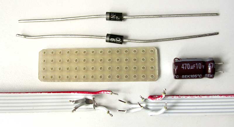
The components I used. Everything is assembled on a small piece of perfboard. The cable here uses 1mm pitch ribbon cable (see bottom of page here for more details), but you can use a split NXT cable (regular or flexicable). A two wires flat cable (not shown here) is used for supply output. |
|
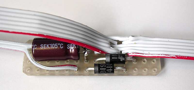
The assembled board, top view. Each matching motor wires are connected together... |
|
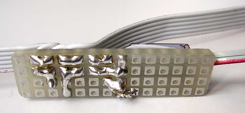
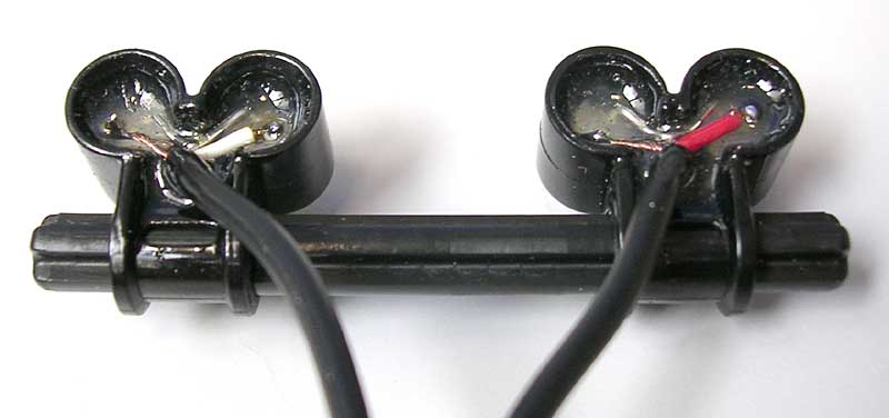
...as shown on this solder side view. |
|
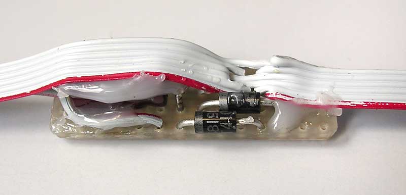
The cables are hot-glued to prevent early breaking. |
|
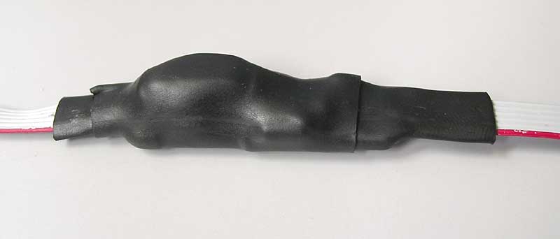
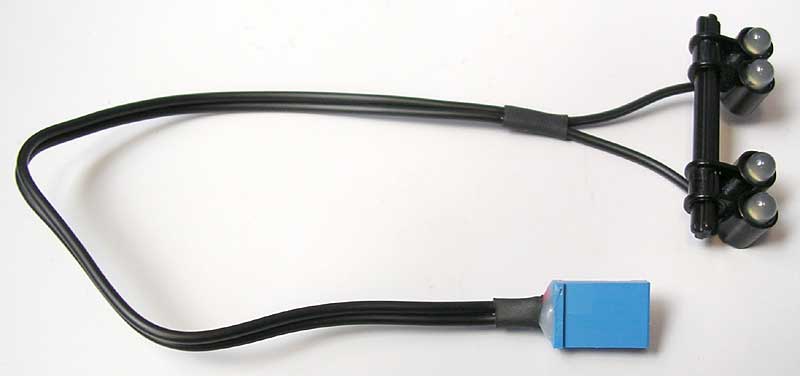
Then everything is protected by heat-shrink tubing. |
|
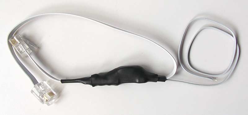
The completed cable. |
|
Video showing NXT controlling and powering 5 motors through only 1 sensor and 1 motor ports (Divx 5, 750ko) |
Alternate construction
|
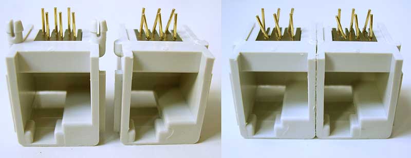
The first version of my NXT power derivation was not built as a cable, but as a little PCB with 2 NXT sockets. These can be obtained from Mindsensors. The sockets have 2 staggered rows of pins with a 2mm pitch, not so easy to use with 2.54mm perfboard. But with a little persuasion (bending pins and cutting retainer pegs) they can be mounted. |
|
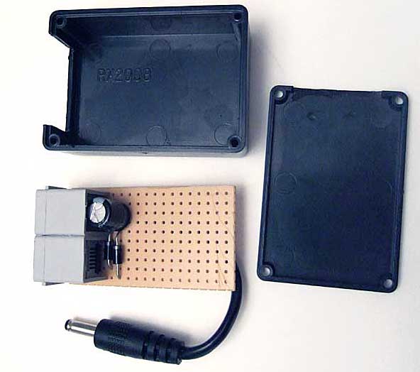
The schematics is the same as the simple cable. This photo shows the PCB next to the small plastic box that will receive it. Instead of a bare cable output for a motor multiplexer, this one is fitted with a jack to power my little wireless camera. |
|
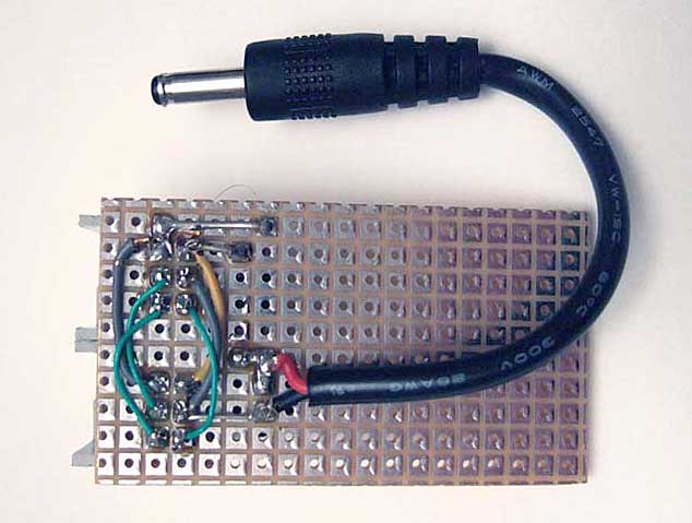
Bottom view of the PCB. Both NXT sockets are connected in parallel. |
|
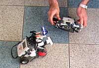
The prototype during testing before box assembly. One NXT socket is connected to NXT port A output, the other is connected to camera orientation motor of my spy rover. See also here. The derived power supplies the wireless camera. |
Advance
regulated version
When I first tested the above cable with my camera, using a NXT equipped with NiMH batteries (low voltage on cable output), I got nothing on TV, so I figured out that voltage was insufficient for the camera. I started thinking adding a step-up switching regulator to boost voltage, with the added benefit of providing a stable power for illumination LEDs that I intended to add to my camera for looking in dark corners. So even when I realized that the camera did work at low voltage (but I had to trim again tuning that shifted with voltage) I went on this version.
The schematics above can be divided in three
sections, the port A supply derivation on left, the switching
step-up regulator in the middle, and connectors to power camera
(J5) and LEDs (J3/J4). Two resistors (R3/R4) limit current in
the LEDs. Assuming a 3.5V drop per white LED, current is about
20mA.
|
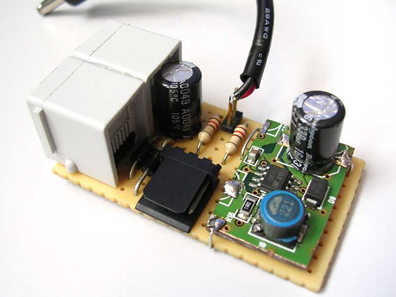
The completed board. As the assembly of a switching regulator on perfboard may be tricky (noise problems), I used a radical solution: the complete regulator was sawn out from an old ADSL board! All I had to do was changing feedback resistors (R20-R21) to modify output voltage from the original 12V to 9.5V. 9.5V was used to make sure the requested output voltage is higher than regulator input voltage. |
|
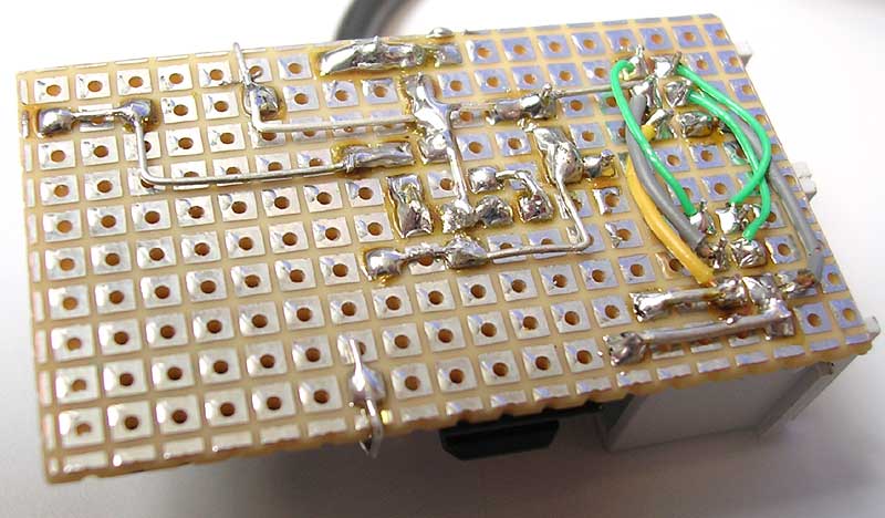
Board bottom. |
|
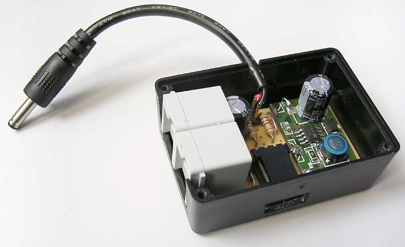
The board inserted in the box. Power to the camera is provided by the jack on top, J3 LEDs connector is in front of a hole in the side of the box. |
|
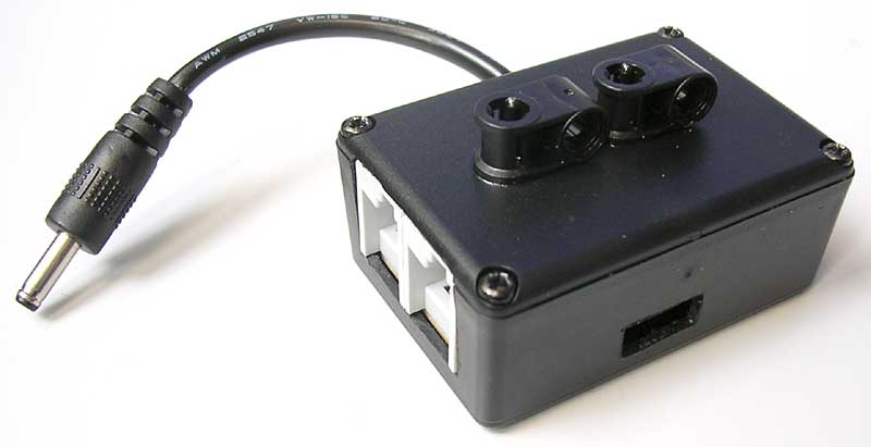
The completed adaptor. Two "axle joiner perpendicular" are epoxy-glued to the box to allow integration to NXT models. |
|
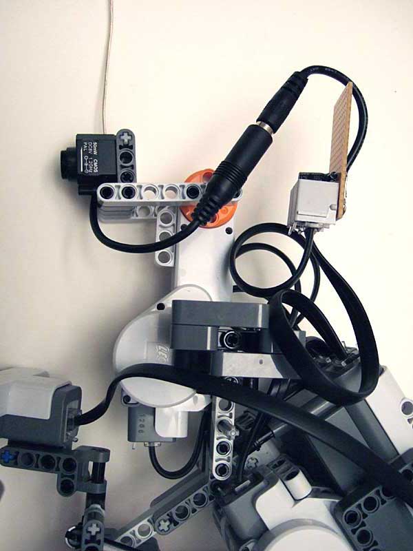
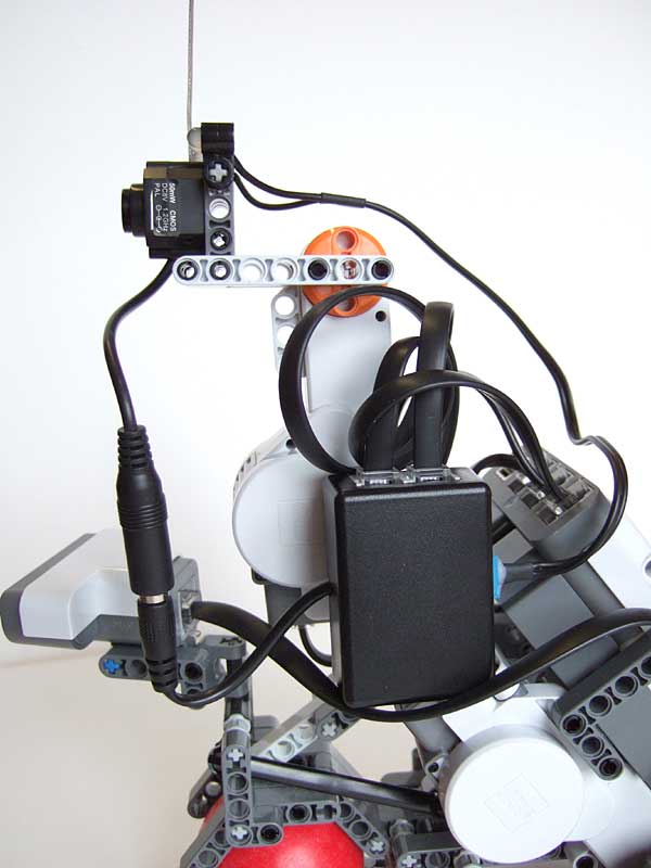
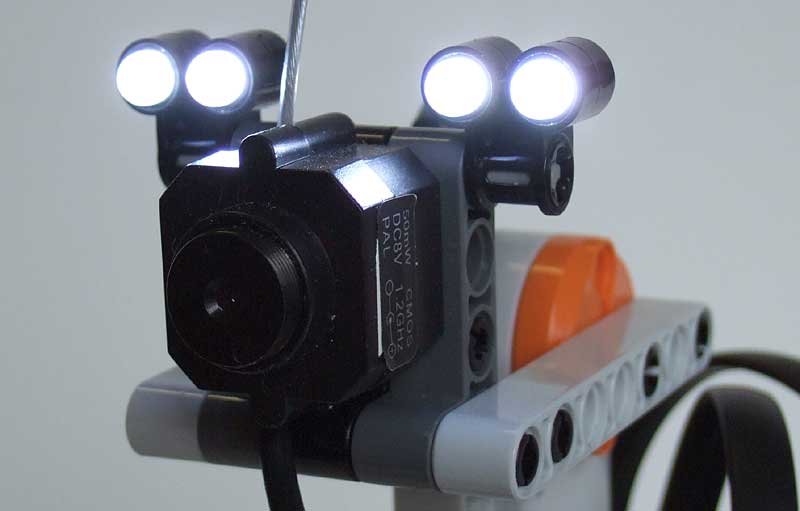
The spy rover, equipped with the supply adaptor. One NXT socket is connected to NXT port A output, the other is connected to camera azimuth orientation motor. See also here. The derived power supplies the wireless camera as well as the four headlights. |
|
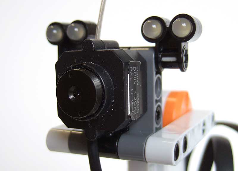
Close-up of the camera with the headlights. |
|
Same photograph with powered LEDs. |
|
Video showing the rover equipped with Port A power adaptor, wireless camera and headlights. The rover is controlled with NXTiiMote. |
White LEDs headlights construction
|
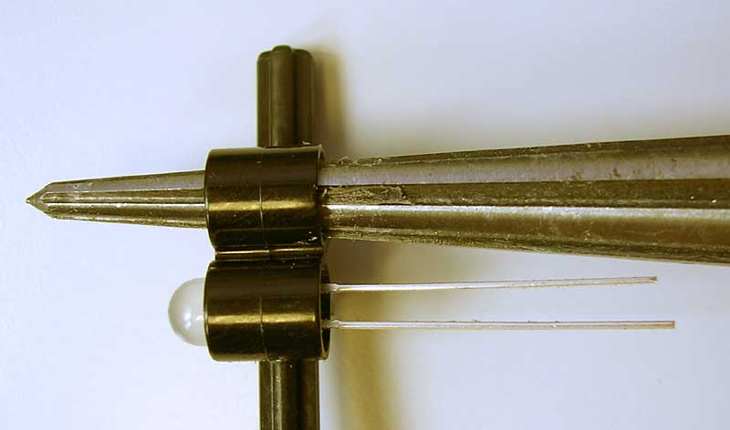
LEDs are inserted into "Axle joiner perpendicular double". The 5mm diameter white LEDs I used where a bit large to fit Technic holes, I had to enlarge them. |
|
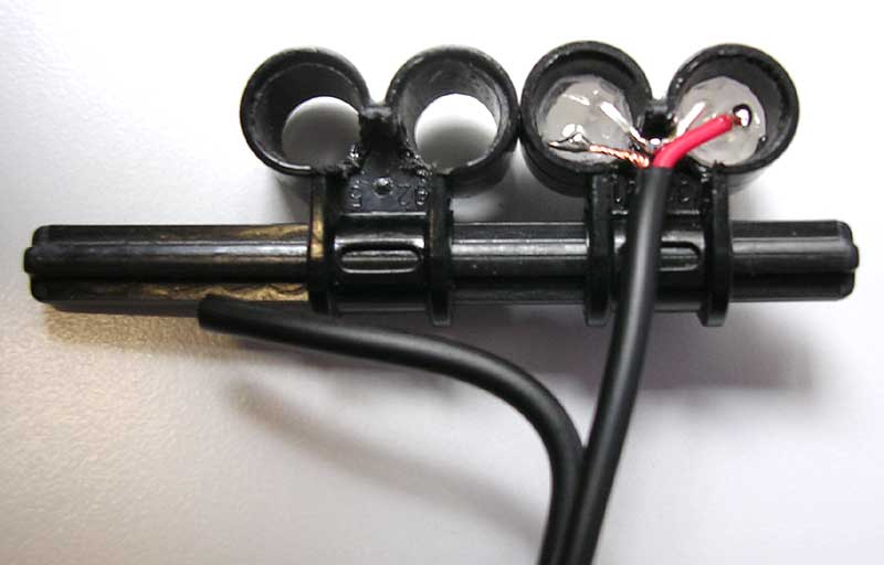
I used stereo audio cable to connect to the serially connected LEDs. |
|
To protect solder and maintain cables, a drop of epoxy glue is placed in each hole. |
|
The completed LEDs cable, ready to plug into the advanced power derivator. |
![]()
![]()
![]()
![]()
![]()
![]()
![]()
![]()
![]()
![]()
![]()
![]()
![]()
![]()
![]()