![]()
![]()
![]()
![]()

![]()
![]()
![]()
![]()
![]()
![]()
![]()
![]()
![]()
![]()
![]()
- V1.1: Initial release
- V1.2: Improved file output format (July 2008)
- Prepare the input LDraw pattern file. Pattern file may contain lines, triangles and quads, as well as flat primitives (see details below). Other LDraw line types are ignored. For good results, each projected element as well as its origin must reside entirely onto a single triangle/quad of former shape. Stamping occurs in Y direction, which means that the pattern file must be in X-Z plane.
- The 3D former file only deals with triangle and quads. Primitives must be inlined down to tri/quads. LDDesignPad does this very conveniently. Other LDraw line types are ignored. Stamping occurs in Y direction, which means that the 3D form must be mostly in X-Z plane.
- Launch a command prompt
- Type the command line: projector LdrawPatternFile Ldraw3DFile Ldraw3DPatternFileOut. Projector will create Ldraw3DPatternFileOut, containing the raised pattern surface. Note that if file Ldraw3DPatternFileOut exists it will be overwritten without warning.
- Projector outputs file with 6 digits after decimal point, this precision is excessive for most usages and values should be rounded. Here again, LDDesignPad does that very well.
- 3D former file is read and parsed. Triangles and quads expanded to triangles are stored in arrays (limited to 1000 lines, should be more than enough!).
- Pattern file is then processed one line at a time. For
each apex of lines/triangles/quads, y coordinate of the
3D former at (x,z) point is calculated. (x,y,z) is then
the 3D coordinate of the resulting apex. For primitives,
projection of the primitive origin is calculated. Orientation
of the 3D file facet that contains the projected origin
is then used to construct the transformation matrix of the
projected primitive. This is meaningful only for flat primitives
that extend in x-z plane. It is the case of all disc, ndisc
and ring primitives.
Note that if a 3D former facet doesn't exist under a pattern point, this point will get (x,0,z) coordinates. - Transformed lines are written one at a time in the output file.
|
Projector,
a LDraw stamping tool
Note: I have created a new tool, SlicerPro, that not only does the projection but also slices the pattern along the edges of the former polygons. No more tedious careful manual alignment!
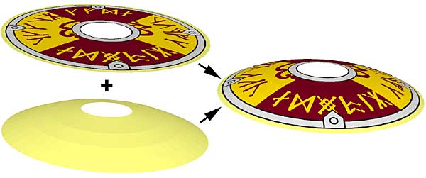
Projector utility allows to stamp a flat pattern over a 3D former. Each set is provided to the utility as separate LDraw files. A third file containing the raised pattern is created.
It is a simple console application, source code is provided below to anyone willing to integrate it in a more palatable user interface.
Download
Projector package, including program for Windows, documentation, source files (Visual C++ 6.0), sample files.
History
Usage
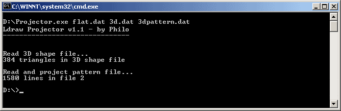
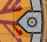
Here is a screen shot of a sample run:
How Projector works
Example: building a Viking shield
|
3960s03, that contains the front of the shield, is inlined and cleaned up with LDDP to obtain 3D.dat file. files: 3960s03.dat, 3D.dat |
|
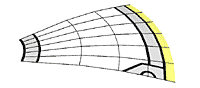
Using MLCad, 3D file is flattened. Hires primitives (whose resolution match 3960 one) are drawn for the shield circles. This allow neat drawing. These primitives are then inlined with LDDP. file: shield1.dat |
|
This LDraw file is converted to Quad2Dat format using Dat2QP. We then open this file in Quad2Dat and draw the four rivets (actually I created only 1/2 rivet with Quad2Dat and duplicated the result with MLCad, then converted again the final file with Dat2QP). We obtain a template file which will be used with the 4 different Viking shields. Command line: Dat2QP shield1.dat shield1.qp files: shield1.qp, shield-template.qp |
|
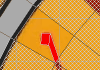
Now begins the tedious part. Each blank facet of the original template must be replaced with the polygons forming the original pattern. As each polygon in the pattern will be projected on a facet of the underlying former, it must be completely enclosed in a single template facet. Note that red is used instead of dark red here: Quad2dat exports "complex" colors as separate LDraw files, which is not very convenient. Global color replacement will fix that later. |
|
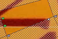
Especially, one must use the "Along line" feature of Quad2dat to align pattern vertices with edges of template facets. Don't rely on eye to place vertices on edge, that would result in warped quads, holes in pattern, overlaps... After the loooonnng manual vectorisation process, we obtain the final pattern... file: shieldpatternflat.qp |
|
We now export the result in LDraw format. Some quads of the original pattern were not removed and they overlap pattern, this is cleaned by duplication/rotation using MLCad of some correct quads done with Quad2Dat. file: shieldpatternflat.dat |
|
Flat pattern is now stamped on the former, using Projector. Command line: Projector shieldpatternflat.dat 3D.dat shieldpattern3d.dat file: shieldpattern3d.dat |
|
To keep file size low, the pattern is separated into subparts, using color selection in MLCad. At the same time red color that was used during the vectorisation is replaced with dark red, and grey is changed into silver. file: 3960p07b.dat |
|
The second subpart, shared with other Vikink shields. This subpart also contains conditional lines extracted from original shield design. file: 3960p07a.dat |
|
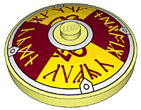
Here is the final result, the completed shield. file: 3960p07.dat |


![]()
![]()
![]()
![]()
![]()
![]()
![]()
![]()
![]()
![]()
![]()
![]()
![]()
![]()
![]()