![]()
![]()
![]()
![]()

- V1.0: Initial release
- V1.1: Transition curve purely linear for -ts 1 instead of approximation.
- V1.2: Added -e option for a better control of direction of start and end section of the generated sheet, added -i option to invert the curvature of generated shape when it appears inside out, increased threshold to avoid creation of degenerated surface elements.
- Prepare the two LDraw path files. PathTruder uses only lines of input files (line type 2). Other LDraw line types are ignored. If you want to extrude surface between edge primitives, they must be inlined down to lines. LDDesignPad or Inliner do this very conveniently. For best results, the lines forming the paths must be connected end to end without gaps. They may form a close loop. Order of lines in file doesn't matter since they are sorted before use.
- Prepare the LDraw shape file. This file is also composed of LDraw lines (line type 2). Other LDraw line types are ignored. The first line of the shape is special as it defines where the shape attaches to the path lines. This first line MUST reside in the XY plane for proper results, and in most applications the whole shape file will be defined in that plane.
- Launch a command prompt
- For basic use, type in the command line: Pathtruder -p1 LdrawPathFile1 -p2 LdrawPathFile2 -s1 LdrawShapeFile LdrawExtrudedFileOut. PathTruder will create LdrawExtrudedFileOut containing the surface. Note that if file LdrawExtrudedFileOut exists it will be overwritten without warning.
- The full syntax, with all options, is: Pathtruder -p1 LdrawPathFile1 -p2 LdrawPathFile2 -s1 LdrawShapeFile1 [-s2 LdrawShapeFile2] [-tn <number>] [-ts <slope>] [-tp <position>] [-c <crease angle>] [-a] [-ra <rotation angle>] [-rs <slope>] [-rp <position>] [-l <length>] LdrawExtrudedFileOut
- -p1 <LDraw path file 1> defines the main path
- -p2 <LDraw path file 2> defines the secondary path
- -s1 <LDraw shape file 1> defines the shape to be swept along the path
- -s2 <LDraw shape file 2> defines the ending shape. If -s1 and -s2 are defined, the shape is progressively morphed between these shapes along the path. This transition can be controlled with -t options:
- -tn <number> sets the number of transitions from shape1 to shape2 and vice versa. 1 (default) sweeps from s1 to s2, 2 from s1 to s2 then back to s1, and so on.
- -ts <slope> controls transition curve, from 1 (linear) to 10 (s-shape, default) to 100 (step)
- -tp <position> controls transition curve centering. 0 <= position <= 1. Default is 0.5, centered
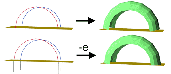
- -e Use path start and end segments to define orientation of corresponding extruded section
- -i Invert curvature of shape
- -c <crease angle> If path has a sharper angle, a line is created at the junction. Default is 180° (no line). Use a negative value to force line creation.
- -a When specified, shape is elongated to compensate for flattening at sharp path angles. Default is no compensation.
- -r <rotation angle> specifies rotation of shape direction vector around path1 as it sweeps along the path. Default is 0°.
- -l <length> define maximum path segment length. Longer segments are split
- PathTruder outputs file with 6 digits after decimal point, this precision is excessive for most usages and values should be rounded. LDDesignPad does that very well.
- Input files are parsed. Lines (type 2) of each files are stored into arrays. Path files are sorted. If only one shape is specified, it is copied to the other to simplify processing.
- if -l <length> option is specified, path lines longer than <length> are split. The same number of splits is applied to both files to keep number of segments identical.
- Shape files are normalized. They are scaled and rotated in XY plane so that direction vector (first line in shape file) is transformed into vector (0, 1, 0). Of course this means that direction vector must have a length > 0.
- Extrusion is then performed. As we move along path lines,
we do the following steps at each path vertex:
- First the shape at that point is calculated. It is an average between shape1 and shape2, weighted by a S-shape function.
- For each point pair in path, a local basis is calculated. Y vector is defined between matching points of path files. An average path normal is obtained from position of path points before and after, and Z vector is calculated as the cross product of this normal with Y vector. Finally, X vector is Y x Z.
- This local basis is scaled so that Y vector has a length equal to point pair distance.
- Coordinates of the shape points are calculated, from this local basis and the averaged shape.
- If the path make an angle greater than -c crease angle, the lines of the local shape are sent to the output file
- Quads joining each shape line to matching line from previous path point are then considered. If the quad is planar enough and not degenerated, it is sent to output files, otherwise triangles are used. In the special case where line length is null in both shape1 and shape2 inputs, a line is created.
|
PathTruder,
a LDraw path extruder
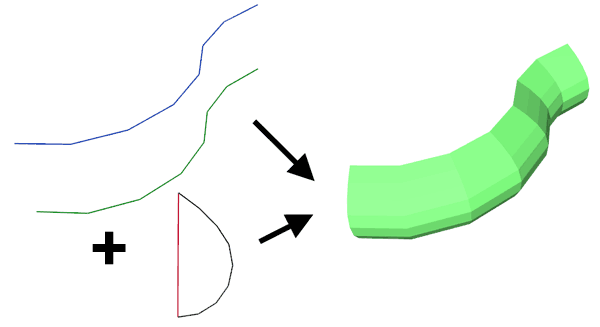
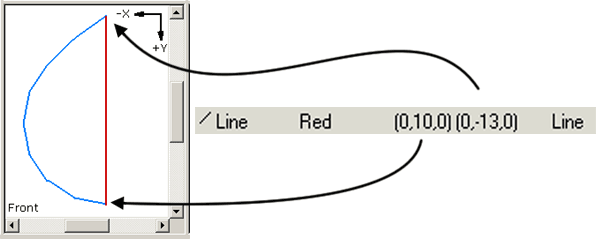
PathTruder utility allows to create a surface by extrusion of a shape along a path. The path is defined as two sets of lines, provided to PathTruder as two LDraw files. The shape, also a set of lines, is the third required input file. The fist segment in shape file (in red in the image above) defines how the shape file is attached to the path, one extremity is applied onto the first line, the other onto the second line.
PathTruder can be considered as a variant of Coverer, not restricted to straight junction of sheet. Though it has many more possibilities, it also has some restrictions - for example Coverer allows the two path lines to have a different number of segments. Another difference is that PathTruder doesn't cerate conditional lines. You'll have to use Edger2 for that.
It is a simple console application, source code is provided below to anyone willing to integrate it in a more palatable user interface. You may also use Michael Heidemann LETGUI front-end (highly recommended!).
Download
PathTruder package, including program for Windows, documentation, source files (Visual C++ 6.0), sample files.
History
Usage
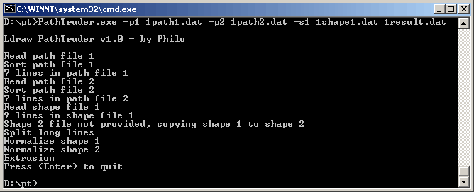
Here is a screen shot of a sample run:
How PathTruder works
Tips and examples:
|
The first line of the shape is special as it defines where the shape attaches to the path lines. This first line (the shape direction vector) MUST reside in the XY plane for proper results, and in most applications the whole shape file will be defined in that plane (exception to that rule occur for spiral shapes, see example below). See file: 1shape1.dat |
|
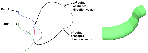
First point of shape direction vector is applied on path1 line, second point of shape direction vector is applied on path2 line. Command line: PathTruder -p1 1path1.dat -p2 1path2.dat -s1 1shape1.dat 1result.dat |
|
The path lines need not be parallel, they may even meet at end points. Command line: PathTruder -p1 2path1.dat -p2 2path2.dat -s1 2shape1.dat 2result.dat |
|
Path may form one closed loop. It is important in that case that there is no extraneous line outside the loop (otherwise the sorting algorithm would fail). Command line: PathTruder -p1 2loopath1.dat -p2 2loopath2.dat -s1 2shape1.dat 2loopresult.dat |
|
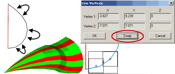
Orientation of segments in shape file is important (a segment should end where the next starts): orientation of generated facets depends of that. MLCad "Swap" button (in line editing window) can help correcting that. Command line: PathTruder -p1 2path1.dat -p2 2path2.dat -s1 2badbfcshape1.dat 2badbfcresult.dat |
|
When two shape files are specified, a morphing is done between these two shapes as we sweep along the path. Here 3shape2 is obtained from 3shape1 by flattening it. Command line: PathTruder -p1 3path1.dat -p2 3path2.dat -s1 3shape1.dat -s2 3shape2.dat 3result.dat |
|
We can control the speed of transition with -ts parameter. This one can vary from 1 (linear transition) to 10 (S-shape transition, default value) to 100 and more (steep transition). Command line: PathTruder -p1 3path1.dat -p2 3path2.dat -s1 3shape1.dat -s2 3shape2.dat -ts 1 3resulta.dat PathTruder -p1 3path1.dat -p2 3path2.dat -s1 3shape1.dat -s2 3shape2.dat -ts 10 3resultb.dat PathTruder -p1 3path1.dat -p2 3path2.dat -s1 3shape1.dat -s2 3shape2.dat -ts 100 3resultc.dat |
|
The -tp parameter controls the position of the transition. Defaut value is 0.5 Command line: PathTruder -p1 3path1.dat -p2 3path2.dat -s1 3shape1.dat -s2 3shape2.dat -tp 0.2 3resultd.dat PathTruder -p1 3path1.dat -p2 3path2.dat -s1 3shape1.dat -s2 3shape2.dat -tp 0.5 3resulte.dat PathTruder -p1 3path1.dat -p2 3path2.dat -s1 3shape1.dat -s2 3shape2.dat -tp 0.8 3resultf.dat files: 3resultd.dat, 3resulte.dat, 3resultf.dat |
|
The -tn parameter controls the number of transition between shape 1 and shape 2. Defaut value is 1 (morphing from shape 1 to shape 2). -tn 2 will go from shape 1 to shape 2 and back, and so on. Note that compared to previous example shape files were swapped to start "flat" Command line: PathTruder -p1 3path1.dat -p2 3path2.dat -s1 3shape2.dat -s2 3shape1.dat -tn 1 3resultg.dat PathTruder -p1 3path1.dat -p2 3path2.dat -s1 3shape2.dat -s2 3shape1.dat -tn 2 3resulth.dat PathTruder -p1 3path1.dat -p2 3path2.dat -s1 3shape2.dat -s2 3shape1.dat -tn 4 3resulti.dat files: 3resultg.dat, 3resulth.dat, 3resulti.dat |
|
The -c parameter controls the path angle above which a line is inserted at the junction between surfaces. Default is 180° (never insert line). You may use a negative value to force line insertion, regardless of path angle. Command line: PathTruder -p1 4path1.dat -p2 4path2.dat -s1 4shape1.dat -c 180 4resulta.dat PathTruder -p1 4path1.dat -p2 4path2.dat -s1 4shape1.dat -c 90 4resultb.dat PathTruder -p1 4path1.dat -p2 4path2.dat -s1 4shape1.dat -c 10 4resultc.dat |
|
If you look at the left image above, you will see that external envelope is not parallel to the path. This is because of the steep path angle, causing an apparent flattening of the shape (length of triangle side is shorter than hypotenuse...). The -a switch causes a shape enlargement to compensate for this effect. Command line: PathTruder -p1 4path1.dat -p2 4path2.dat -s1 4shape1.dat 4resultd.dat PathTruder -p1 4path1.dat -p2 4path2.dat -s1 4shape1.dat -a 4resulte.dat |
|
You may also control if and where lines should be created along extrusion. To do that, you insert a null length segment in the shape file (if two shape files are specified, a null length segment must exist in both files). Command line: PathTruder -p1 5path1.dat -p2 5path2.dat -s1 5shape1.dat 5result.dat |
|
The -l parameter allows to refine a path by limiting the maximum length of line segments. Lines longer than specified length will be split in equal-length segments. Command line: PathTruder -p1 3path1.dat -p2 3path2.dat -s1 3shape2.dat -s2 3shape1.dat -tn 4 3resulti.dat PathTruder -p1 3path1.dat -p2 3path2.dat -s1 3shape2.dat -s2 3shape1.dat -tn 4 -l 2 3resultj.dat |
|
With the -r parameter, you instruct PathTruder to rotate the direction vector during the sweep, to allow creation of spiral and twisted shapes. The shape above could be the basis of the modelling of Barbed Wire Coil for which I added this feature... Command line: PathTruder -p1 6path1.dat -p2 6path2.dat -s1 6shape1.dat -r 360 6result.dat |
|
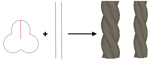
Another example (courtesy of JC Tchang) using the -r parameter: creation of string sections. Old LEGO strings (1980) have about a 0.8mm diameter (2ldu), modern ones are 0.6mm (1.5ldu), and are composed of three braided threads. In command line, -r parameter must be followed by torsion angle (here 360°, one full turn). In this example path lines are 6ldu long and spaced 1ldu for '80s version, 0.75 ldu for recent cables. A smaller value of l parameter improve result quality but increase file size. Anyway files tend to be big and it's better to create only short string segments. Command line (old string): PathTruder -p1 string_p1a.dat -p2 string_p2a.dat -s1 string_sec.dat -r 360 -l 0.5 string_l05_r360.dat Command line (recent string): PathTruder -p1 string_p1a.dat -p2 string_p2b.dat -s1 string_sec.dat -r 360 -l 0.5 string_l05_r360.dat |
|
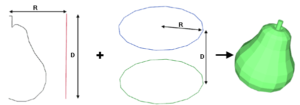
It is easy to create surface of revolution with PathTruder. As path lines, choose two parallel circles with radius R, distant from D. The shape direction vector must be of length D to avoid scaling. Then the distance between part of the shape that will become surface axis and the direction vector must be D. Command line: PathTruder -p1 7path1.dat -p2 7path2.dat -s1 7shape1.dat 7result.dat |
|
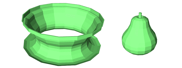
Proper orientation of generated sheet depends on the way you have created the shape file and on the direction of path files. If the result you get seems inside out, use -i option to invert curvature of the shape file (new in version 1.2). Command line: PathTruder -p1 7path1a.dat -p2 7patha2.dat -s1 7shape1.dat 7resulta.dat PathTruder -p1 7path1a.dat -p2 7patha2.dat -s1 7shape1.dat -i 7resultb.dat |
|
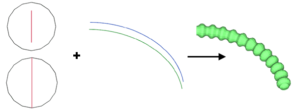
Using the multiple shape transition, it is easy to create corrugated tubes that follow path lines. Here the shapes are identical circles, but since the size of the direction vector is different, we get alternating shrinking/dilatation. You may play with the -tp and -ts shape transition parameters to get the desired result. -l length parameter can help split the path lines to get enough resolution. Command line: PathTruder -p1 8path1.dat -p2 8path2.dat -s1 8shape1.dat -s2 8shape2.dat -l 2 -tn 24 8result.dat |
|
A back and forth transition between two shapes can create this nice boat hull. Now I have to admit that tweaking parameters to match a real part can be... tricky! Command line: PathTruder -p1 9path1.dat -p2 9path2.dat -s1 9shape1.dat -s2 9shape2.dat -tn 2 9result.dat |
|
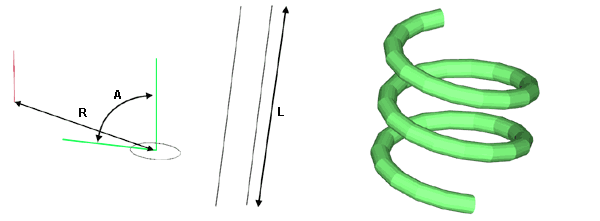
PathTruder can also create springs, thanks to its -r option. Using -l option to split lines, each path file can be a single segment. The smaller the -l parameter, the finer the result will look - and the bigger resulting file will be! At the opposite to most uses, the shape must be at an angle with direction vector. If R is spring diameter, L the length of the spring, n the number of turns, the angle of shape plane with direction vector should be A = atan(n*2*PI*R/L). Command line: PathTruder -p1 10path1.dat -p2 10path2.dat -s1 10shape1.dat -r 900 -l 0.5 10result.dat |
|
The -e "endings" option enables a better control of the end section of the generated sheet. To use it, you must add "tail" segments at both ends of path files. The start of extruded sheet will be perpendicular to the plane defined by these tails. In this example it is used to create a surface that meets a plane. Command line: PathTruder.exe -p1 11path1.dat -p2 11path2.dat -s1 1shape1.dat -e 11result.dat PathTruder.exe -p1 11path1e.dat -p2 11path2e.dat -s1 1shape1.dat -e 11resulte.dat |
|
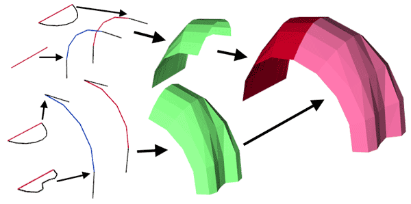
You may also use -e to ease joining of several sections of PathTruder work. Command line: PathTruder.exe -p1 12path1.dat -p2 12path2.dat -s1 12shape1.dat -s2 12shape2.dat -e -i 12result1.dat PathTruder.exe -p1 12path3.dat -p2 12path4.dat -s1 12shape3.dat -s2 12shape2.dat -e 12result2.dat |
![]()

![]()
![]()
![]()
