![]()
![]()
![]()
![]()

![]()
![]()
![]()
![]()
![]()
![]()
![]()
![]()
![]()
![]()
![]()
- Get NQC program for the wire-guided roverbot.
- See two Quicktime video clips:
Complete circuit, 4x accelerated movie (330K).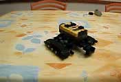
Closer look, real time (230K).
Wire guidance sensor
When I visited Legoland Deutchland, I wondered how vehicles circulating in Miniland were guided. Though I don't know the exact method used by Lego, I figured out that they could use inductive guidance. And I began experimentations to create an RCX wire guidance sensor...
For another very cute guidance system, based on magnets and iron track, see Pascal Breard Brickshelf Gallery.
Principle
An AC current flowing in a wire generates a magnetic
field, stronger near the wire. This field is picked up by two
coils, the difference is amplified and adapted to RCX.
Wire guided vehicles are used for years in industry, so a quick search on the Web returns lots of information on this technique. For example, AGV Electronics has a detailed description of inductive guidance.
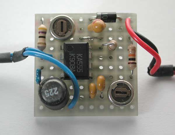
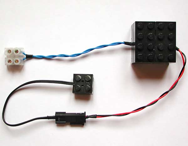
Generator
The creation of the current requires an AC generator. Its frequency is chosen high enough to be easy to pick up with small coils, but low enough to use low cost components and not to generate electro-magnetic interferences in the vicinity. A 50 KHz frequency gave fine results. This generator is powered by a 9V battery pack, and its low power consumption (about 20mA) provides a good autonomy.
Circuit
analysis
This circuit is very simple: a NE555 timer generates
a square wave which is converted to a sinusoidal wave with L1/C1
tuned circuit. R2 is used to trim frequency. I added R1 to ajust
wave level, but setting R1=0 works fine so you can omit it.
D1 protects the circuit from reversed power supply. Note that
you can use L1=10mH, C1=1nF (same values used for the detector),
the values I used for my prototype were chosen before building
the detector, where I discovered that the higher inductor value
(which provides beter sensitivity) was really a boon.
You can see here a simulation of this circuit operation, obtained with Circuit Maker Student.
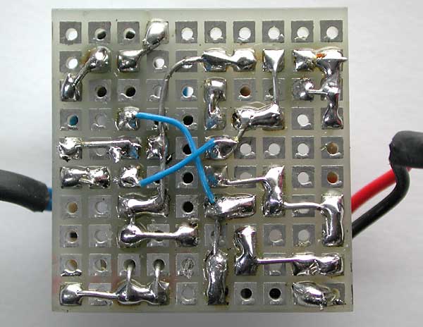
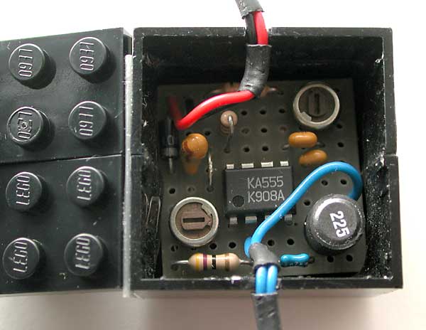
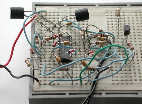
Construction
|
|
|
|
Sensor
Circuit
analysis
Electromagnetic field generated
by guidance wire is picked-up by left and right coils L1 and
L2. L1 and C1 are tuned on generator frequency (50kHZ). IC1B
and D1 forms a no-threshold rectifier and amplifies signal.
R3 and C2 filters output, so we get here the amplitude of input
signal.
The other side is processed identically with IC1C, D2, R4 and C3. Left and right amplitude signal are then substracted by IC1D and converted to a variable current with Q1 and R14. IC1A and D3 creates a 0.6V virtual ground for IC1B and IC1C, and an offset voltage to shift output of substractor IC1D.
D4, D5 and C5 creates the filtered power supply from RCX sensor port.
You can see here a simulation of this circuit operation, obtained with Circuit Maker Student.
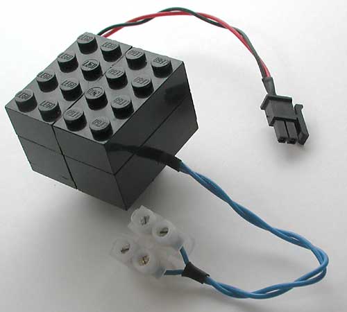
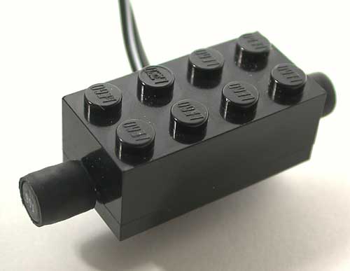
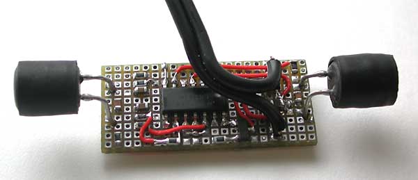
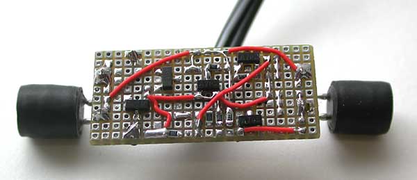
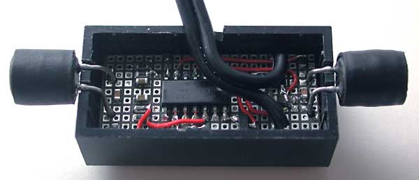
Construction
To challenge my soldering capabilities, I assembled sensor
using SMD components... This was a really tough job, but I was
able to fit everything (except the inductors bulging out) in
a single hollowed 2x4 brick !
|
|
|
|
Component
selection
No component is really critical here, LM324 is a very
common quad op-amp, any NPN small signal transistor (BC548,
2N2222...) will be OK for Q1, and 1N4148 can be used for all
diodes. Inductors may be slightly more difficult to find, I
used 22R106 inductors I got from RS-components
(ref. 173-5915).
Sensor
testing
This sensor can be used as a light sensor, to test it
simply program the RCX sensor port as "light sensor"
and display its output on LCD screen using "view"
button. Without generator, RCX should read about 65. Fix a small
loop of wire (30cm or so) between generator terminals, and move
the wire near coils. The wire must be perpendicular to coil
axis (case 2 on figure below. Position 1 yields a weaker signal.
There is no field collected at all in case 3).
With wire near one coil, reading should be lower than no-field value, and it should raise above when over the other coil. Now adjust R2 on the generator to get maximum variation. With loop wire in close contact with coils, it should be easy to saturate sensor (value=0 on one coil, value=100 on the other). The sensor works well with a distance between sensor and wire of more than 1 cm, allowing to hide track below a short pile carpet or some other decoration.
The sensor detects nothing when the wire is parallel to coils (case 3 above). This may cause problems with very tight turns, but can be used to create self-crossing wire tracks. This works very well provided that the cross makes a 90° angle.
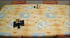
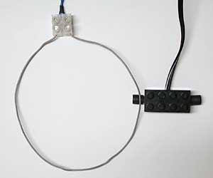
Test robot
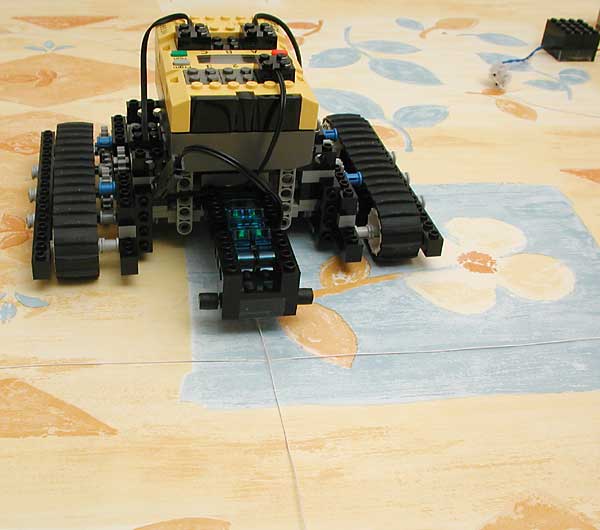
A simple roverbot equipped with the wire guidance sensor follows a track made with a thin wire taped on a table.
![]()
![]()
![]()
![]()
![]()
![]()
![]()
![]()
![]()
![]()
![]()
![]()
![]()
![]()
![]()