![]()
![]()
![]()
![]()

![]()
![]()
![]()
![]()
![]()
![]()
![]()
![]()
![]()
![]()
![]()
- test_color_sensor.nqc: displays 3 digits on LCD, corresponding to RVB reflected levels.
- Brick Sorter 3: see it here !
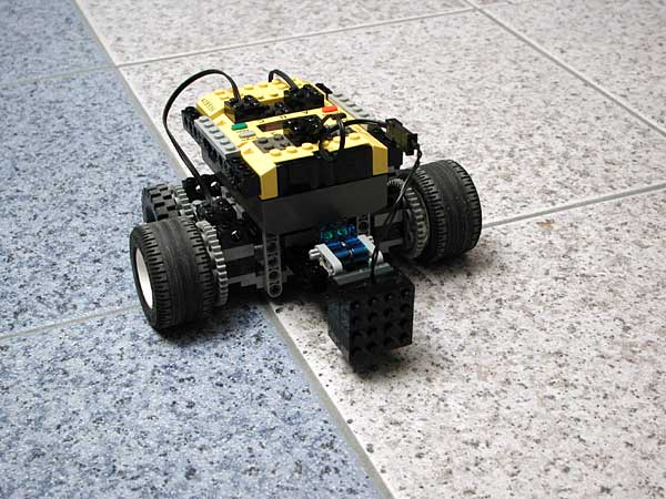
- Color follower: when I was a Mindstorms newbie, I tried the roverbot-and-light-sensor line follower on my tiled floor. Unfortunately there is not enough contrast between tiles to be able to get a reliable working. With the color sensor, the difference between blue and red channels enables to tell blue from grey tiles and is relatively independent of ambient light level. The robot must be slow though because of the time it takes to cycle through color sensor states.
Get NQC program for the color follower.
Color sensor
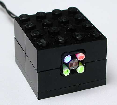
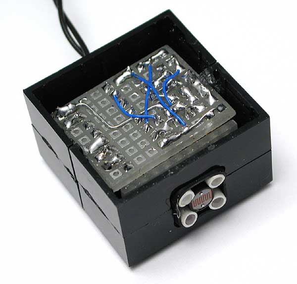
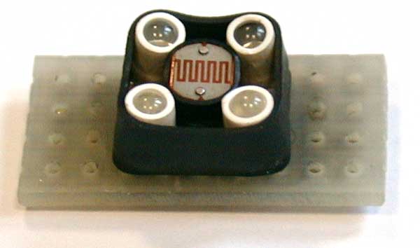
I built this color sensor to equip my third implementaton of brick sorter. Michael Gasperi presents such a sensor in an article of Nuts and Volts magazine. His circuit is based on an input multiplexor. Three CdS photo-resistors, connected to this multiplexor, receive light through RGB colored filters (cleverly done with Lego transparent bricks).
This one takes a somewhat opposite route: a multiplexor (similar to Michael's) drives three RGB leds that cast light onto the object. Reflected light is measured by a single photo-resistor. Another (non-Lego) home built color sensor, based on the same idea, can be found in David Cook's robotics pages.
Circuit
analysis
The heart of this circuit is a CD4017 (IC1), CMOS counter
with decoded output. On each pulse received on its clock input,
this IC drives high the next output (all the other are driven
low).
 Output 0, 1 and 2 drives
red, green and blue LEDs through transistors Q2, Q3, Q4 (emitter
follower is used to avoid the need of a base resistor). During
the first three phases, output 4 is driven low and provide ground
reference for photo-resistor R8: the RCX can read light level
reflected in each color. In phase 4 photo-resistor is no longer
grounded, value returned to RCX is maximum (note the 1 Mohm
resistor paralleled with R8 to prevent maximum value to be reached
in phases 1/2/3). RCX can detect this special condition and
synchronize its readings to CD4017 state.
Output 0, 1 and 2 drives
red, green and blue LEDs through transistors Q2, Q3, Q4 (emitter
follower is used to avoid the need of a base resistor). During
the first three phases, output 4 is driven low and provide ground
reference for photo-resistor R8: the RCX can read light level
reflected in each color. In phase 4 photo-resistor is no longer
grounded, value returned to RCX is maximum (note the 1 Mohm
resistor paralleled with R8 to prevent maximum value to be reached
in phases 1/2/3). RCX can detect this special condition and
synchronize its readings to CD4017 state.
The oscilloscope hard-copy shows clock pulse
on top trace, output 1/2/3 below.
 To generate a clock pulse,
you have to switch from active sensor mode (sensor voltage is
higher than Zener D4 threshold, Q1 is conducting, clock input
is low) to passive sensor mode (sensor voltage is lower than
D4 threshold, Q1 is blocked, clock input is high) and back to
active sensor. C1 filters out short power supply pulses occuring
in active mode evey 3ms while RCX reads value.
To generate a clock pulse,
you have to switch from active sensor mode (sensor voltage is
higher than Zener D4 threshold, Q1 is conducting, clock input
is low) to passive sensor mode (sensor voltage is lower than
D4 threshold, Q1 is blocked, clock input is high) and back to
active sensor. C1 filters out short power supply pulses occuring
in active mode evey 3ms while RCX reads value.
The oscilloscope hard-copy shows clock pulse
on top trace, sensor voltage on bottom trace showing 2 short
reading pulses and wide command pulse generated by sensor mode
switching.
When reaching step 5, CD4017 activates D04 and reset itself
to step1 through R4/C3. This RC network delays reset pulse well
after clock transition: without it, the current rush of the
LED, coupled through power supply, modifies clock threshold
and CD4017 goes directly to step 2...
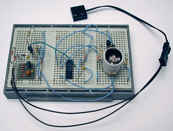
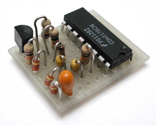
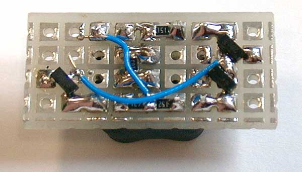
Power supply is rectified by D1 and filtered
by C2. As in my other sensors, I keep on with single diode instead
of full bridge to minimize components count (3 diodes instead
of 8!) but as you can see I built the breadboard with a full
bridge module I constructed to ease my prototypes.
|
|
Component selection
Nothing is really critical: D1 to D3 are small signal diodes
(i.e. 1N4148), Q1 to Q4 are general purpose NPN transistors
(BC548, 2N2222...). Photo-resistor I used is a MPY54C569
(any similar size LDR will probably work fine). Leds are high
efficiency 3mm ones. I used Agilent: red HLMP-K105
for D5, blue HLMP-KB45
for D8, green HLMP-1540
for D6 and D7. I was somewhat disappointed by green Leds efficiency.
Though the photoresistor has its peak sensitivity around green
wavelength, read value was fairly low with green lighting. After
testing different Led types and brands, I finally chose to use
two green leds with maximum current. Even then color sensor
sometimes has troubles to distinguish between green and black
(!) Lego bricks... Green bricks reflects surprisingly very little
light, I guess the problem is that my green leds have a too
yellowish wavelength. Most of the components were bought from
Farnell.
Led current is limited by R5, R6 and R7. To set their values, I placed the breadboard in front of a white piece of paper and adjusted them to get about the same reading for all colors.
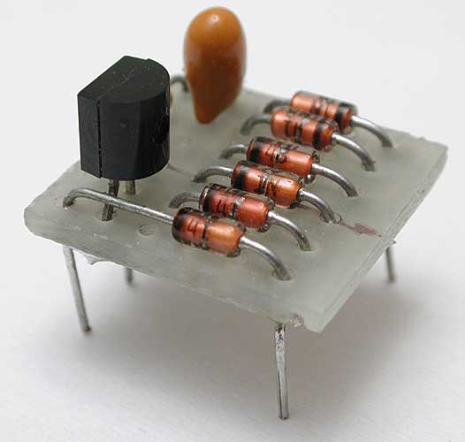
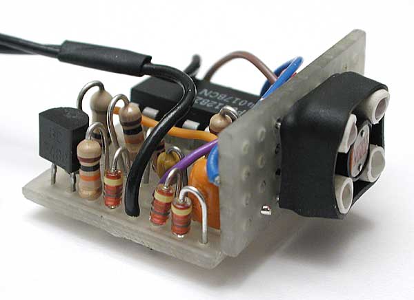
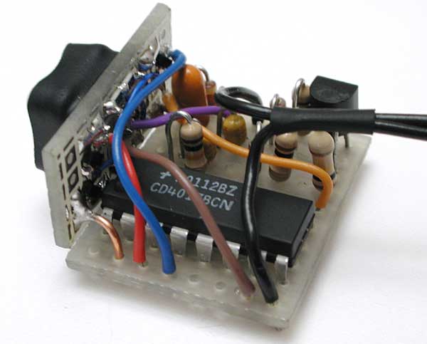
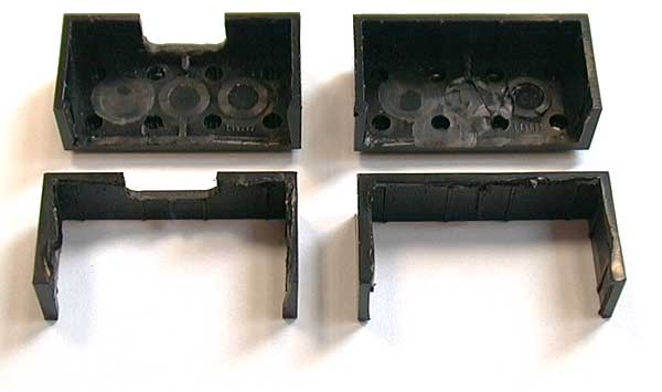
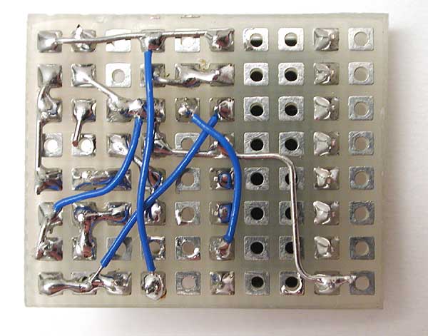
Building color sensor: photo gallery
|
|
|
|
Test programs
![]() test programs (requires
RCX 2.0 firmware that you can get here)
test programs (requires
RCX 2.0 firmware that you can get here)
Real applications
|
|
![]()
![]()
![]()
![]()
![]()
![]()
![]()
![]()
![]()
![]()
![]()
![]()
![]()
![]()
![]()