![]()
![]()
![]()
![]()

![]()
![]()
![]()
![]()
![]()
![]()
![]()
![]()
![]()
![]()
![]()
- Width = 13.9mm
- Height = 7.5mm
- Overall length = 13.7mm
- Plugged depth = 5.85mm
- Pitch = 1.27mm
- Cable width = 7.5mm
- Cable thickness = 1.2mm
The Powered
Up connector
This connector first appeared in WeDo 2.0 set (45300) in 2016. It allows to connect sensors and motors to the controller. This 6-wire system progressively replaces the Power Functions 4-wire system. This system was initially named "Power Functions 2.0" but it was then used in 2017 Boost Creative Toolbox (17101), 2019 Powered Up trains, and 2019 Control + Technic sets, so naming this system remains... tricky! But as of publishing, it looks like LEGO gathered these avatars under the common "Powered Up" banner.
Mechanical details
|
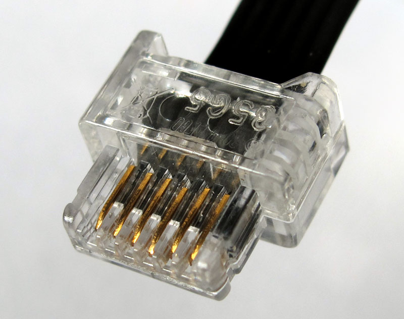
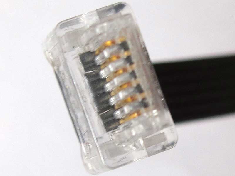
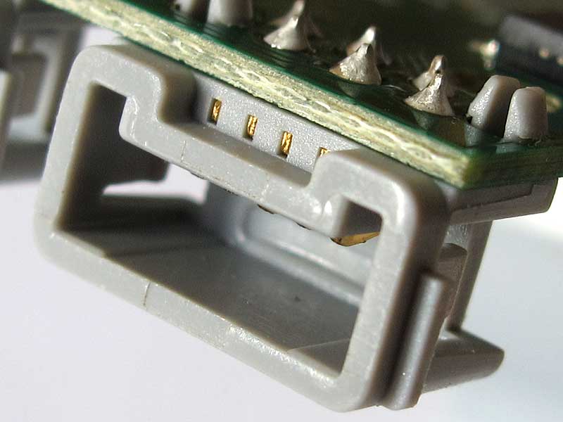
The plug is - afaik - LEGO proprietary. Fortunately connector contact pitch is standard, at 1.27mm. Dimensions: As you can see on the first photo, the third contact (used for ground connection) is a tad longer, allowing the ground connection to be established before other ones. This can avoid some electrical problems during "hot plug". |
|
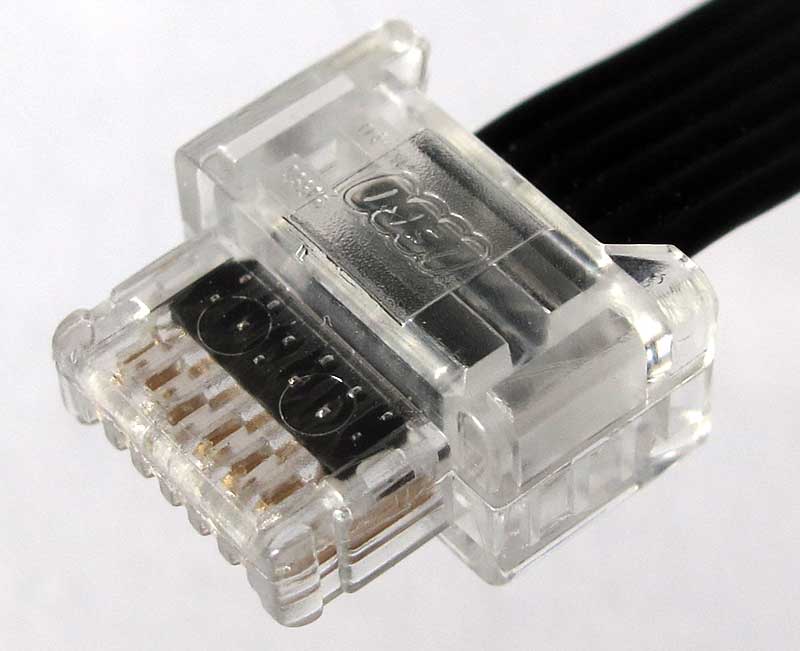
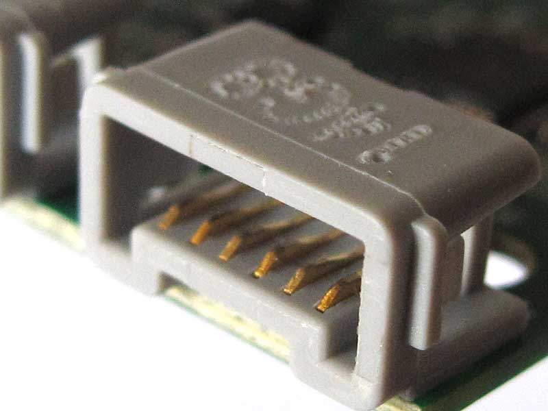
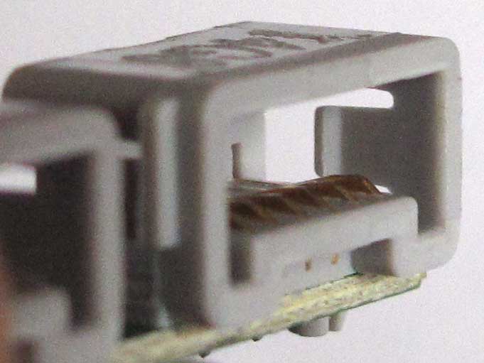
The socket. The third photo shows the retainer latch that goes in the side notches of the plug to provide some "clutch power" between plug and socket.
|
Pinout
Pin |
Label |
Function |
1 |
M1 |
Motor power lead 1 (PWM controlled) |
2 |
M2 |
Motor power lead 2 (PWM controlled) |
3 |
GND |
Ground (0V) |
4 |
VCC |
Power for device electronics (3.3V) |
5 |
ID1 |
Analog identification line 1 / Serial data (hub -> device) |
6 |
ID2 |
Analog identification line 2 / Serial data (device -> hub) |
Note that even if power supply for device electronics is 3.3V, motor PWM is at battery voltage for Powered Up, 5V for WeDo 2.
ID1/ID2 function
ID1/ID2 pins have different function depending on the type of devices. For "dumb" ones (those that don't contain a controller), they are hard-wired to GND/VCC, either directly or through resistance, to provide an analog style identification. For devices containing a controller (sensors, motors with position encoder), ID1/ID2 are used as a serial link between the hub and the device. ID1 transmits data from hub to device, ID2 from device to hub. More details in Powered Up serial protocol.
Here is the table showing wiring of analog identification style devices:
Device |
Label |
Wiring |
Powered
Up simple motor |
ID1 |
GND
through 2.2 kOhm resistor |
Powered Up train motor |
ID1 |
VCC |
LED |
ID1 |
GND
through 2.2 kOhm resistor |
![]()
![]()
![]()
![]()
![]()
![]()
![]()
![]()
![]()
![]()
![]()
![]()
![]()
![]()
![]()