![]()
![]()
![]()
![]()

![]()
![]()
![]()
![]()
![]()
![]()
![]()
![]()
![]()
![]()
![]()
- Choose the part to model. Geometrical shapes are not interesting to build through 3D scan, the models created this way contain a lot of triangles so this process is best for organic shapes, as you can see in gallery above.
- The laser line on the object must be clearly visible by the camera. The part must be lightly colored and without patterns. Otherwise you need to "paint" it in white color. I generally use a chalk spray paint, but white tempera with a drop of detergent works too. You'll then need to carefully clean the object after scanning with a fine brush!
- In a darkened room, calibrate your camera (see details in DAVID manual)
- install the object on the scanner and start scanning. You will need to perform scans from various directions, to make sure you completely cover the object. Some areas not covered by scan may be acceptable provided the object is smooth there, the reconstruction process will fill the holes. Make sure there is enough overlap between scans to ease object reconstructions later. Save all the partial 3D views for later processing.
- load all the partial scans in ShapeFusion
- the first step will be to clean the scans, removing parasitic shapes (eg. the supporting axle) and the fuzzy edges of the scan where the laser line or camera viewing direction were almost tangent to the shape.
- align all the scans. If there is enough overlap, the automatic process works well. Otherwise you will need to use manual alignment tools, much more time consuming...
- once you are happy with the patchwork of partial scans, do a Poisson reconstruction... and you now have the raw shape, with a huge number of triangles.
- when looked closely, real part edges are not so sharp
- the scanning process has limited resolution
- white paint tend to accumulate in the holes, partially filling them.
|
3D Laser Scanner
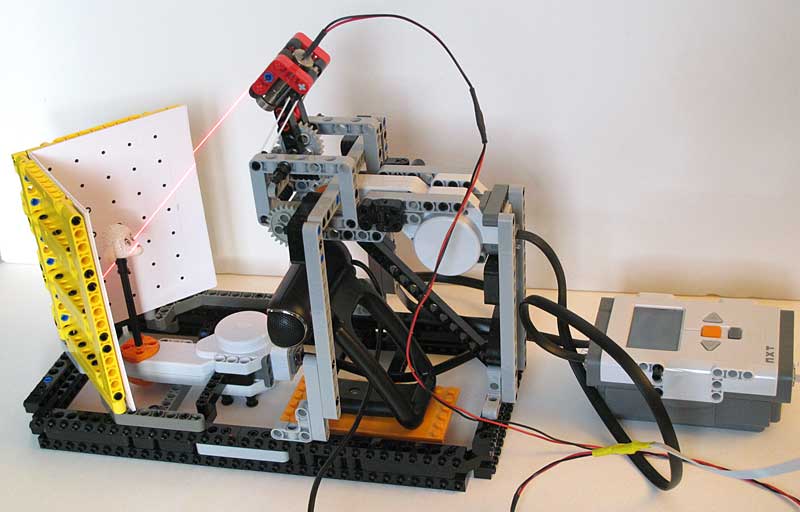
Though my NXT 3D probe scanner was quite successful, it suffered from a big drawback: it was slooooow! I then discovered DAVID-3D laserscanner. This software gem allow to reconstruct 3D shapes with a line laser and a webcam! Even better, the free version is quite usable with some limitations: resolution is low, and you have to use MeshLab to assemble the scans together to rebuild the complete shape.
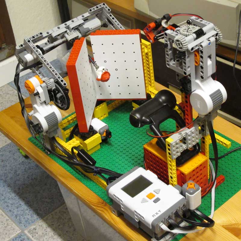
Even though you can sweep the laser line on the scanned object by hand, you'll get better scan quality with a very regular and low speed sweep. I built this NXT contraption for that.
|
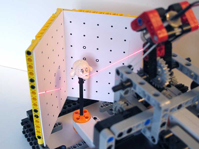
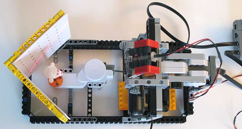
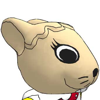
Here you see the heart of the action. The red laser line slowly sweeps the object (here a Fabuland lamb head). Behind the scanned object, two planes with a 90° angle provide reference to the scanning software. They are also marked with regularly spaced black dots that serve during the calibration process that inform scanning software of webcam characteristics, field of view, optics distortion... |
|
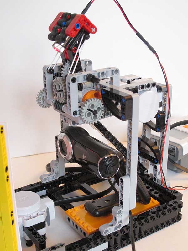
The laser sweeping mechanism. The NXT motor is down-geared by 1:2880, providing a really slow motion. The two white rubber bands maintain tension on the gears to avoid gear lash. The NXC code allows to set the scan speed through motor speed variation, and to move the laser at maximum speed during scan setup. Below the sweeping mechanism there is a Logitech Pro 9000 webcam. This high quality webcam provides very good images, thus detailed scans (though I made my first tries with a much lower cost Trust webcam). The drawback of this webcam is that it doesn' have a screw mounting hole, here is how I added one. |
|
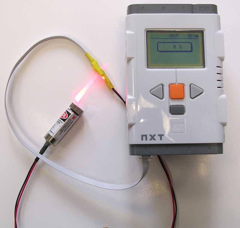
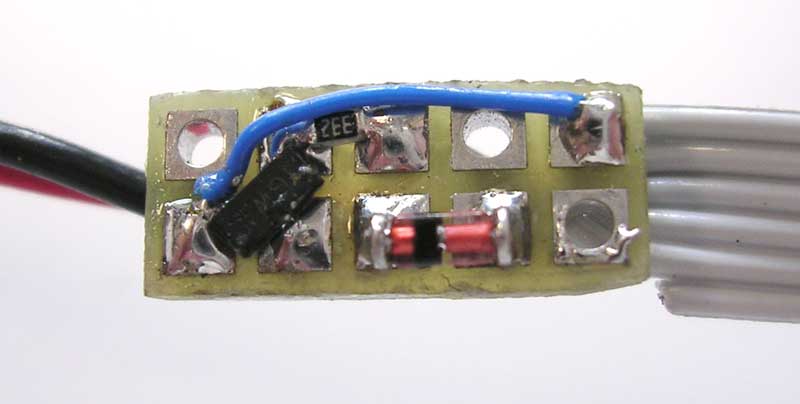
The laser itself is powered from the NXT through a sensor port. The small interface board in the middle of the cable contains a transistor to switch the laser on/off (the same way as the LED of NXT light sensor) and a series diode to lower voltage. The laser is a red laser module with focused line that I bought from DealExtreme. |
|
Close-up of the laser control interface. |
|
Schematics of the control interface. D2 is a small silicon diode (1N4148) whose purpose is to lower voltage on the laser, since lightly loaded NXT IO supply can exceed the 4.5V maximum rating of the laser used. Q1 is a small NPN transistor (BC548, 2N3904...) used to control laser with DIGI0 NXT I/O pin. This is the same circuitry as the one used in the LEGO light sensor to control the red LED, so the laser can be controlled the same way. Program the port as a reflected light sensor to light up the laser, and as an ambient light sensor to put it off. |
|
Top view of the scan bench. The second NXT motor is able to rotate the object to acquire different angles of view. It would be necessary to be able to tilt the object to see above and under. Unfortunately I have not yet found a way to do this without blocking camera sight on the panels behind. So I replace straight axle mount with assemblies containing angle connectors. |
|
Update: I have built another version of the scanning hardware that allows tilting of the object for easy scanning above and below. |
Video
Programs
|
The program is very simple, you first choose scan speed, then pressing orange button you go to the main scanning screen..The laser lights up. Pressing the right or left NXT key allow you to start scan in up or down direction. Pressing left or right for a more than one second toggle to high speed mode to pre-position laser line before actual scan. Pressing orange button again, you go to the object rotation mode that allows to turn the object by 45° increments. Orange again comes back to scan mode. |
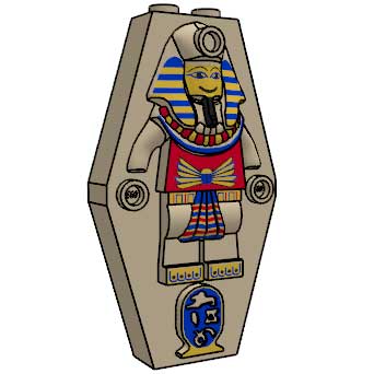
LDraw gallery
Here are a few LDraw parts that I created with the help of laser scanner.
|
|
|
|
|
|


From object to LDraw
Here is a very quick overview of the long and winding road going from physical LEGO parts to its LDraw model.
If you have the full version of DAVID, you may use its ShapeFusion tool to reconstruct the object
If you have only the free version of DAVID, ShapeFusion doesn't allow you to save the reconstructed result. You'll have to use MeshLab for that. I have written a tutorial about that here. This tutorial is based on an old version of MeshLab, recent version works better (especially the matching points based alignment tool). You may have to experiment a bit...
One problem with scanned parts is that the edges are not as sharp as they should be, because
To be able to place outlining LDraw edges, you need to enhance locally sharpness of the mesh. Sculptris does wonder for that. Import the mesh you obtained from scan as a .obj file, and use the crease tool to sharpen angles where needed. The smooth tool maybe handy too if you see small irregularities in an area that should be smooth.
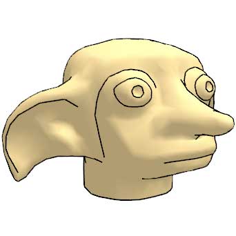
The next step with be to down-sample the mesh. Raw scan contains some 20000 triangles and after Sculptris enhancement this figure can rise in the 1000000 range. A good value to target for a LDraw file is about 3000 to 5000 triangles. MeshLab decimation filter works great for that. Load scanned part in MeshLab, then apply Filters > Remeshing, simplification and reconstruction > Quadric Edge Collapse Decimation. Choose the target number of faces and click apply. Check then if the result is detailed enough and if you have triangle edges where you intend to place outlining LDraw edges. Misplaced edges may require to go back to Sculptris and sharpen the edge even more. If the result is not detailed enough, you may also increase the number of triangles. It is also possible to use several different resolutions in various places of the part. For example, in Dobby's head the eye appeared blocky and the mouth was blurred. I first reduced the overall mesh to 10k triangles, selected eyes and mouth, inverted selection and further reduced mesh size on selection to 3500 triangles. I then had enough details in the eyes while keeping mesh size down.
When you are happy with the result, it's time convert to LDraw. In MeshLab, save the file in stl file format. Don't forget to uncheck "Binary encoding", then convert the resulting .stl file to LDraw using Stl2dat. After that you just have to do regular Parts Tracker preparation, similar to the one you have to do on LEGO Universe Team parts...
![]()
![]()
![]()
![]()
![]()
![]()
![]()
![]()
![]()
![]()
![]()
![]()
![]()
![]()
![]()