![]()
![]()
![]()
![]()

![]()
![]()
![]()
![]()
![]()
![]()
![]()
![]()
![]()
![]()
![]()
- we start at full CCW position (PWM set at full forward, servo mechanical stop, load weight is at lower position). Angle is about 0°
- at t=2s, we send to the servo the order to go to full CW position (PWM set at full reverse, load weight is lifted at upper position). Angle is about 180°
- at t=4s, we send to the servo the order to go to neutral position (PWM set at 0°)
- at t=6s, we go again to full CCW position.
- at t=8s, return to neutral.
No load
4.3 N.cm
8.5 N.cmWe see from these charts that - as expected - power consumed by servomotor increases with torque applied. Spikes of current at 8.5N.cm load reaches 600mA.While the servo soon reaches a position close to the target, it struggles more and more to reach it as load is increased.
Shaft angle curves under various loadsOn this chart, I have plotted the three shaft angle curves under various loads. We see that there is a small dead time between the order and the rotation start (about 0.12s). It then takes about 0.12s to rotate 90°. The total reaction time is thus about 0.25s for a 90° angle change, 0.36s for a full 180°. There is little speed change with increased load to reach a good approximation of target angle, the final settling time does increase significantly. We can see also that the final angle depends on the load. I don't know if this is caused by poor regulation, play in internal gearing of the servo, or elasticity in my own test bench.
LEGO® Power Functions Servomotor
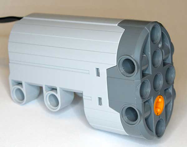
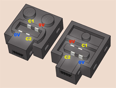
This Power Functions element appeared first in 2012 Rock Crawler set (9398), used for steering. Like RC servos, its output turns within a limited range (-90° to +90°) in response to a control signal. Being a Power Functions range member, it is fully integrated with this system, and receives its commended position through C1/C2 lines, and its power from supply lines. On a normal motor, C1/C2 duty cycle directly control motor speed, here they set the angular position of the shaft.
This article details the behavior of the PF servomotor and how well it performs.
See also this excellent video presentation by Sariel.
Test setup
The setup is similar to the one I use to compare motors. The servo is powered by a laboratory power supply, through a Mindsensors PowerMeter sensor used to measure current. A Hitechnic Angle sensor monitors shaft angle. Weight lifting provides the load - with a little drawback, the load is always applied in the same direction... C1/C2 lines of the servo are directly connected to measuring NXT port B, allowing a full control of the servo by varying "power level" (actually, PWM duty cycle) on this port. Here is a sample of the NXC programs that I used during the tests.
Proportional?
One of the first question that was asked when the servo appeared was: "does it provides proportional action, or only right/center/left positioning"? efferman soon posted a video showing a proportional control when using PF speed controller. But this device only generate discrete speed steps - what happens between steps?
My setup using NXT to control C1/C2 lines allows to set any PWM duty cycle between -100% and +100%... and as shown in the video below, the PF servo has only seven positions on each side of neutral.
Servomotor behavior
The servomotor is exercised with the following script:
Overload
If we continue to increase load on the servo shaft, new things happen, as shown on the curves below. Blue curve is current consumed, red curve is angle variation at no load, drawn as reference. Pink curve show shaft angle at full load.
12.8 N.cm, 9V supply.
Reaching target angle is now much longer, about 1.7 seconds to go from -90° to +90°. But the real difference is that the servo doesn't hold on the target angle! As soon as target angle is reached, we see that the load drives the shaft back to -90° position. This means that once the servo has reached its target, it doesn't try to correct and maintain its position anymore, as a regular RC servo would do. And most probably, it doesn't even brake the motor by shorting it (or only briefly). The load can thus relatively easily back drive the servo, once the internal friction is overcome.
12.8 N.cm, 7.2V supply.
The above chart shows the same heavy load test, this time performed with a 7.2V power supply (the nominal voltage of 6 AA NiMH cells). We see that even at this low voltage the servomotor is quite powerful (only the ramp-up is slower), and of course we see the same back drive by the load.
An other way of overloading the servomotor is to block its normal travel.
+/- 45° blocked
travel
In the above chart, I put two stops on each side of the servo travel, limiting it to +/-45°. We see that after a short normal move to reach 45° (at low current since there is no external load), the servo motor hits the stop. There the current is increased to the maximum (900mA) for a short time (less than 0.25s), then the servo stops trying, and stays idle till it receives an other order. This means that no harm will be done is the servo is accidentally blocked in its travel - of course I don't recommend this as normal practice!
![]()
![]()
![]()
![]()
![]()
![]()
![]()
![]()
![]()
![]()
![]()
![]()
![]()
![]()
![]()