![]()
![]()
![]()
![]()

![]()
![]()
![]()
![]()
![]()
![]()
![]()
![]()
![]()
![]()
![]()
- V1.0: Initial release
- V1.1:
- Now limits expansion to main-colored elements. -m option overrides this.
- Don't select bordering edge lines if -b option is specified.
- Return whole file (-d+) or only key-colored elements to uncolored state (-d)
- V1.2:
- Bug correction: using discolor (-d, -d+) implied -m option
- Bordering condlines are no longer selected if -b option is specified.
- Condlines and edge lines are now sorted separately when -s option is specified.
- Prepare the input LDraw files. Selector only considers surface and line elements (line type 2, 3, 4 or 5). Other LDraw line types are ignored, including subparts or primitives (Selector is mainly aiming meshes coming from LDD or other 3D tools)
- Launch a command prompt.
- Type the command line: selector [-p <val>] [-k <val>] [c <val>] [-s][-x?][-a <val>][-m][-d?][-b]LdrawFileIn LdrawFileOut. Selector will create LdrawFileOut, containing the original file with selected elements colored and optionally grouped at the end. Note that if file LdrawFileOut. exists it will be overwritten without warning.
- Input file is read and parsed, stored in an array.
- Except if -x- option is activated (no expansion of key color) is specified, array is scanned to find surfaces (triangles or quads) adjacent to key-colored ones. These adjacent elements are colored into key color if they are main-colored (color 16). This process is repeated until no other surface gets colored. The method is extremely inefficient, but seems fast enough even with huge LDraw files... To allow expansion on surfaces whose color is different from color 16, use -m option.
- This colored surface expansion is limited by default on edge lines (-xl). If the initial key-colored element is placed in an area completely surrounded by edge lines (beware of leaks!), this area will be completely selected. Alternatively, you can specify -x+ option. In this case, all connected elements will be selected ("connected elements"=surfaces that share a common edge). Expansion may be also limited by sharp angle in surface. This is specified by using -a <angle>. Then all facet junctions that have an angle sharper than <angle> will be an expansion frontier. Note that adjusting the angle value to select what you need may be tricky or impossible. -xl and -a may be used at the same time to limit to edges and sharp angles.
- After expansion, a new scan is done on lines (edge lines
and conditional lines). All the lines that border key-colored
element are colored. Optionnally, if -c
<color> is specified, lines that have a
key colored facet on only one side are colored using that
color instead of key color. The edge lines
(not condlines! in version 1.1)and condlines (from version1.2) may also be omitted from selection if -b option is used. - If you use -s option, all key colored elements will be grouped together at the end of file. Bordering elements (if -c option is used) come first, preceded by the comment "0 // Bordering edge lines" then "0 // Bordering condlines". Then follows the rest of selected elements is preceded by the comments "0 // Key Colored edge lines", then "0 // Key Colored condlines" and finally "0 // Key colored elements".
- -d option allows to return all selected elements to their uncolored state (surfaces into main color 16, lines to edge color 24). -d+ option goes one step further, and removes color from the whole file. Of course, these options can be used only if -s option is specified, otherwise the whole selection process would be pointless ;)
- -p <value> controls the maximum distance between two points that Selector will consider matching.
|
Selector, LDraw mesh selection tool
Selector utility allows to select surface elements by extending a key-colored surface to its neighbours. This expansion can stop on various criteria, meeting of an edge line or of a sharp enough angle, or extend to all connected elements. Edge lines or conditional lines enclosed or bordering selection can be selected too. The selection is done by changing color of elements to key color. Optionally, selection can be moved to the end of output LDraw file.
It is a simple console application, source code is provided below to anyone willing to integrate it in a more palatable interface. You may also use Michael Heidemann LETGUI front-end (highly recommended!).
Download
Selector package, including program for Windows, documentation, source files (Visual C++ 6.0), example files.
History
Usage
Here is a screen shot of a sample run:
How Selector works
Examples
|
The following examples are based on this mesh, a 3D capture from LDD 2421 part. This mesh is actually composed of 4 non-connected areas, the bar, the bar support, the brick and the stud. A few triangles in each area have been colored using MLCad. |
|
Using default options, cylindrical portion of the bar is selected, since source file contained there a dark pink triangle (default key color). The edge lines bordering this area are also selected. Command line: Selector 2921.dat sel1.dat |
|
As you can see, conditional lines of the cylinder are selected too. |
|
If -x+ option is used, the whole bar is selected. Non-connected areas (no common edge) are not selected. Command line: Selector -x+ 2921.dat sel2.dat |
|
In LDD models (as in most LDraw ones!), studs are simply laying on top surface, not connected to it. When you adapt LDD 3D meshes to LDraw, the studs need to be substituted with primitives. Selecting the studs is easy, just color one triangle (here red) in each stud, use -x+ option, and everything composing LDD stud (including lines and conditional lines) can be selected and deleted at once! Command line: Selector -x+ -k 4 2921.dat sel3.dat |
|
When the part contains many studs (eg. baseplates), placing a colored triangle in each stud can be painful! In this case, it is simpler to work negatively, placing a key colored element in each area that is not a stud. Here I will select all green areas, and use -s option to group selected elements to the end of file. As opening huge files in MLCad can be very slow (LDD baseplates reach several megabytes) it may be convenient to remove studs using a text editor! Command line: Selector -x+ -k 2 -s 2921.dat sel4.dat |
|
Here we see the use of -c <color> parameter. The edge line bordering the selected area is now colored differently, allowing to specifically select it. Command line: Selector -c 1 2921.dat sel5.dat |
|
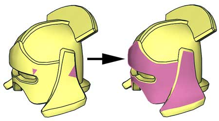
Here is an example showing selection with limit angle (example and image courtesy J.C. Tchang). By limiting the expansion of facet with a 30° angle, we are able to select side of LDD cow model. Command line: Selector -a 30 64780.dat 64780b.dat |
|
Another selection scenario, during conversion of part 98585 from LDD mesh to LDraw. We need to remove peg and axle holes to replace them with primitives. As there are many areas separated by edge lines in axle holes, it may seem a bit tedious to assign a colored triangle in each area! So we are going to use a bit twisted method to simplify things... The first step will be to create a selection barrier on top and bottom of part to "isolate" the holes. 98585a is a quarter of the part (created from LDD mesh using Symsplitter). One triangle on top and one on bottom area is colored blue (key color = 1). |
|
We expand blue area... Command line: Selector -k 1 98585a.dat 98585b.dat |
|
Using MLCad, we add a dark pink element in each hole, result is 98585c |
|
Now, we select dark pink areas (default key color) to all connected elements (-x+). Expansion stops when it meets a surface that is not main color, so blue area will not be selected. Of course, since we have used the sort option -s, we could have used -d+ option to return all elements to uncolored state, but the colored screenshots are more explicit... Command line: Selector -x+ -s 98585c.dat 98585d.dat |
|
We then remove the lines after "0 // Key Colored elements", using LDDP od MLCad. Here is the result (98585e.dat). The hole elements are now completely removed, including condlines (always tricky to remove manually). |

|
![]()
![]()
![]()
![]()
![]()
![]()
![]()
![]()
![]()
![]()
![]()
![]()
![]()
![]()
![]()