![]()
![]()
![]()
![]()

- V1.1: Initial release
- V1.2: Improved file output format
- V1.3: Added -s scaling option. Added code to avoid creation of degenerated quads (vertices aligned)
- V1.4: Used dynamic memory allocation to manage bigger files. Corrected a bug that caused triangles to disappear. Unfortunately another bug remains, I have not found the root cause but when this occurs the message "*** problem during retriangulation ***" is displayed. Prescaling may help in this case.
- Prepare the LDraw file to be cut. Cut file may contain lines, triangles and quads. Other LDraw line types are ignored. Intersector works best if all quads are as flat as possible. Check with PlanarCheck tool.
- The cutter file only deals with triangle and quads. Primitives must be inlined down to tri/quads. Inliner does this very conveniently (LDDesignPad can be used too but it doesn't preserve BFC orientation). Other LDraw line types are ignored. For best results the cutter file should have a well defined orientation with all tri/quads of the same winding.
- Launch a command prompt
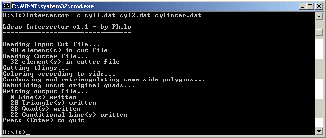
- Type the command line: Intersector [-c] [-t] LdrawCutFile LdrawCutterFile LdrawCutFileOut. Intersector will create LdrawCutFileOut containing the split surface. Note that if file LdrawCutFileOut exists it will be overwritten without warning.
- With -c option, coloring is done according on which side of the cutter blade we are. More details in the next section below.
- With -t option, no condensing of triangle is done after the cut process. File size in facet count is obviously much higher: this option should not be used except for debugging purpose.
- -s option helps with small parts for which default threshold are not adapted. This generally result in missing faces in output file. -s <value> scales up all input files before intersection, and scales down the result in the end.
- Intersector outputs file with 6 digits after decimal point, this precision is excessive for most usages and values should be rounded. LDDesignPad does that very well.
- Input file to be cut is parsed. Lines (type 2), conditional lines (type 5), triangles (type 3) and quads (type 4) split as two triangles are stored into an array.
- Input cutter file is parsed, triangles and quads (split as two triangles) are stored in another array.
- Each element of the cut file is checked against triangles
of the cutter file. When there is an intersection, splitting
is performed as follow:
- lines and conditional lines are split in 2 segments, both stored in the input cut file array. Each receive a tag according on which side of the cutting triangle they are. Note that the control points of conditional lines are transferred without modification to the cut segments.
- Triangles are split into several triangles (1 to
5) according to the position of the intersection. They
also receive a side tag, (side 1, side 2, side unknown).
- All the new elements created by these splits are added to the input cut file array, where they are tested against other intersections.
- After all intersections are calculated, degenerated triangles that might have been created in the process are suppressed.
- If -c option have been specified, elements are colored
according to their side of the "cutting blade".
Original colors are lost, but it makes easier to sort out
elements that must be removed after the cut. Of course,
this coloring is meaningful only if the cutter file has
a clear inside and outside, with all triangles sharing the
same winding. Here is the coloring palette:
Triangles, quads
Lines, Conditional lines
Outside
Turquoise
11
Blue
1
Inside
Yellow
14
Dark Tan
28
Unknown
Gray
7
Black
0
- If no -t option has been specified, triangles from the same original facet and sharing the same side are condensed. For that, a polygon is built by successive addition of adjacent triangles that meet these criteria. In the process, polygon vertices aligned with previous and next vertices are eliminated. This avoids creating T junctions in the final result. This polygon is then re-triangulated into triangles and quads. A simplified process reconstructs quads of the original file that were not modified by the splitting process.
- Finally, the resulting file is written.
|
Intersector,
a LDraw cutter tool
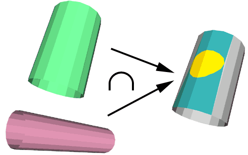
Intersector utility allows to cut a LDraw file along the intersection with another. Each set is provided to the utility as separate LDraw files. A third file containing the cutting result is created. All triangles, quads, lines and conditional lines in cut file are split where they meet triangles or quads of the cutter file. Note that intersection line is not calculated, you'll have to use Isecalc on the same input files to create it.
It is a simple console application, source code is provided below to anyone willing to integrate it in a more palatable user interface. You may also use Michael Heidemann LETGUI front-end (highly recommended!).
Download
Intersector package, including program for Windows, documentation, source files (Visual C++ 6.0), sample files.
History
Usage
Here is a screen shot of a sample run:
How Intersector works
Examples:
|
Cylinder cutting a quad and a line, shown with LDView BFC check mode (inside is red, outside green). Result is on the right. Inside zone is yellow (dark tan for the line), outside is turquoise (blue for line). Intersector could not figure out the side of the two grey colored triangular regions. Command line: intersector -c square.dat cylint.dat cutint.dat files: square.dat, cylint.dat, cutint.dat |
|
Winding of the quads composing the cylinder were reversed, turning inside out. Coloring of the intersection changes accordingly. Command line: intersector -c square.dat cylext.dat cutext.dat files: square.dat, cylext.dat, cutext.dat |
|
When the winding of the cutter file are not coherent (here they were randomly reversed), there is no clear inside and outside. Sorting out the result is much more difficult! Command line: intersector -c square.dat cylrnd.dat cutrnd.dat files: square.dat, cylrnd.dat, cutrnd.dat |
|
Triangle condensing is very effective to clean up the result of cutting process. On the left is the result without triangle condensing (-t option). Command line: intersector -c -t square.dat cylint.dat triangul2.dat files: square.dat, cylint.dat, triangul2.dat |
|
For small parts (cylinder in this exemple here has a 0.8 ldu radius), the thresholds used by Intersector may be unsuitable. The scaling option (-s <scale>) can help. Left image shows Intersector result without prescaling: 2 facets are missing in the yellow area, and there is a teeny gap on right side.. Right image shows the result with -s 3 prescaling: all problems disappeared. Command line: intersector -c a1.dat a2.dat noprescaling.dat
intersector -c -s 3 a1.dat a2.dat prescaling_3.dat
files: a1.dat, a2.dat, noprescaling.dat, prescaling_3.dat
|
- Select everything in the file (Edit/Select/All)
- refresh the screen (View/Refresh). All conditional lines appear, but everything is still selected.
- Click on an empty region of the drawing. You then have deselected everything, but the conditional lines are still visible!
- Now you may select them, either with area selection or control+click on several of them. Note that when you hit Del key to suppress them the screen is refreshed and remaining conditional lines are hidden again.
|
As a more practical use, we shall try to build a smooth cockpit like shape. We start from two intersecting quarter cylinders. files: ws1.dat, ws2.dat |
|
We now create the intersection of ws1 cut by ws2: Command line: intersector -c ws1.dat ws2.dat ws12.dat then ws2 cut by ws1: Command line: intersector -c ws2.dat ws1.dat ws21.dat and, using Isecalc, the intersection line between both files. Command line: isecalc ws1.dat ws2.dat wsline.dat files: ws1.dat, ws2.dat, ws12.dat, ws21.dat,
wsline.dat |
|
The next step is to clean up the files, removing unwanted stuff, here turquoise or blue colored. It is easy for ws1: in MLCad, click on a turquoise surface, select all elements same color (Edit/Select/Same Color) then hit del key. Now select a blue conditional line in the list to and select all elements same color (Edit/Select/Same Color). Hit del key to remove unwanted conditional lines in the cut out part. Dealing with ws2 is a bit harder since some grey stuff remains, here you will have to use area selection to complement color selection. Tip: How to use area selection on conditional lines. MLCad only selects conditional lines that can be seen in the selected area. Here is how to get around this restriction. After cleanup, all remaining elements are re-colored with main color (16) and edge color (24) Files: ws12a.dat, ws21a.dat |
|
After assembling the various subfiles, we get this final result. File: ws.dat |
|
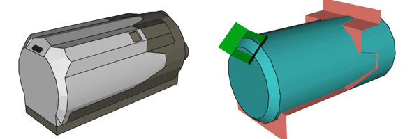
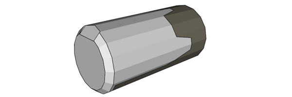
As a more detailed example we are going to build a rough sketch of the Power Functions medium motor. This motor presents two tricky points to model, the zigzag front/back separation line, and the flat surface where the cable attach. |
|
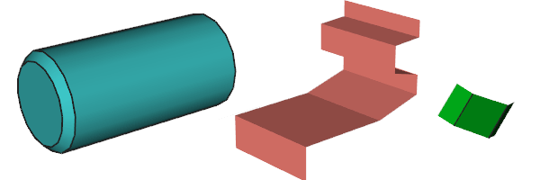
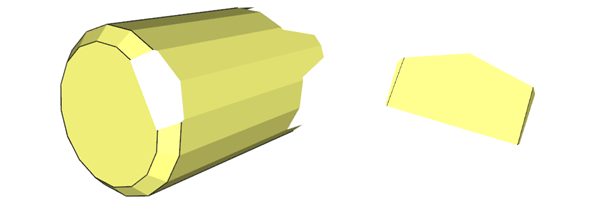
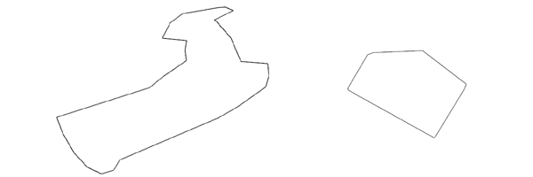
Three elements in separate files will be used: a capped, chamfered cylinder, a zigzag cutting blade and a cable attachment blade. |
|
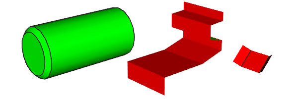
The cylinder elements are inlined using Inliner. With LDView in BFC check mode, we verify that the files are BFC-coherent (adjacent facets have the same color). Files: pf1.dat, pf2.dat, pf3.dat |
|
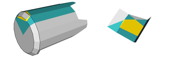
The cut is done: Command line: Intersector -c pf1.dat pf2.dat pfsplit.dat Then, with MLCad using same color selection and area selection, front and back parts are separated. They are also recolored in main color/edge color (this step is not necessary for back part that will be cut again in the next step...) Files: pfsplit.dat, pfback.dat, pffront.dat |
|
Back is now carved to create cable attachment flat. Here we need both surfaces so two intersector operations are needed. Command line: Intersector -c pfback.dat pf3.dat pfback1.dat
Intersector. -c pf3.dat pfback.dat pfback2.dat
Files: pfback1.dat, pfback2.dat |
|
Again, files are separated and recolored with MLCad Files: pfback1a.dat, pfback2a.dat |
|
Finally, intersection lines are calculated with Isecalc: Command line: Isecalc pfback.dat pf3.dat pfbackl.dat
Isecalc pf1.dat pf2.dat pffrontl.dat
Files: pfbackl.dat, pffrontl.dat |
|
All subfiles are assembled and properly colored. Note again that this is only a quick sketch. A true part might also need to separate in two halves to reduce size (this also has the added benefit of a truly symmetrical part, the cutting process doesn't respect this symmetry). Some primitives substitutions where it is possible would be needed too. File: pf.dat |
![]()

![]()
![]()
![]()


