![]()
![]()
![]()
![]()

![]()
![]()
![]()
![]()
![]()
![]()
![]()
![]()
![]()
![]()
![]()
- Clock running time (for those using weight, their maximum travel was fixed to 50cm)
- Proper ratio between seconds hand and minutes hand
- Hour hand with correct ratio
- Quality of cuckoo mechanism
- Aesthetics of the clock and cuckoo
- Originality of mechanisms and techniques used
Cuckoo
Clock
|
In March 2011, the French LEGO Technic forum SeTechnic launched a competition: build a purely mechanical cuckoo clock out of LEGO pieces. The target was to build a clock able to work at least 30 seconds, and in the end have a cuckoo bird going out...
Evaluation criteria:
As building a clock is something I considered for a long time, I decided to participate. The description below is more or less the translation of the text of my submission, describing the design process.
I was lucky enough to win the competition, despite many other valuable entries ;)
LDraw/MLCad file
|
Daniel Weissengruber- FLY(at)gmx(dot)at - created a LDraw file with building steps using my photos - Many thanks, Daniel! Download the LDraw/MLCad MPD file. |
Videos
|
This is the full (rather boring) thing, about 6 minutes of tick-tock. Speaking of tick-tock, time between tick and tock is not 1 second, but 0.625 seconds. For aesthetic reasons, I wanted a simple pendulum, and getting a 2 seconds period implied a 1 meter pendulum - disproportionate in my opinion. But of course seconds hand runs at the right speed! Since clock autonomy is about 6 minutes, I set-up the cuckoo to go out every 3 minutes. This allows for some animation, occuring at t = 2'35" and t = 5' 35" |
|
This video shows working details, with for example a close-up of the cuckoo going out and the mechanism that triggers it. |
|
The final one shows the various modules composing the clock, their testing and their progressive integration to the clock. |
Photos
|
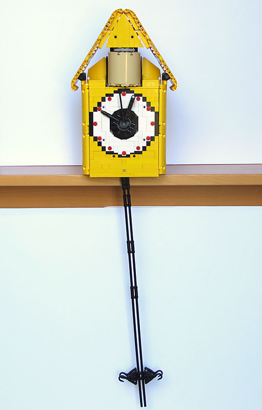
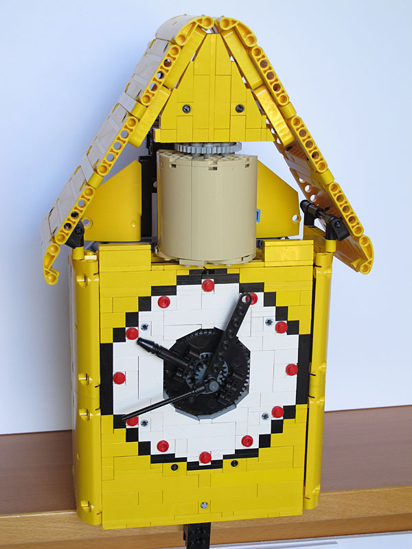
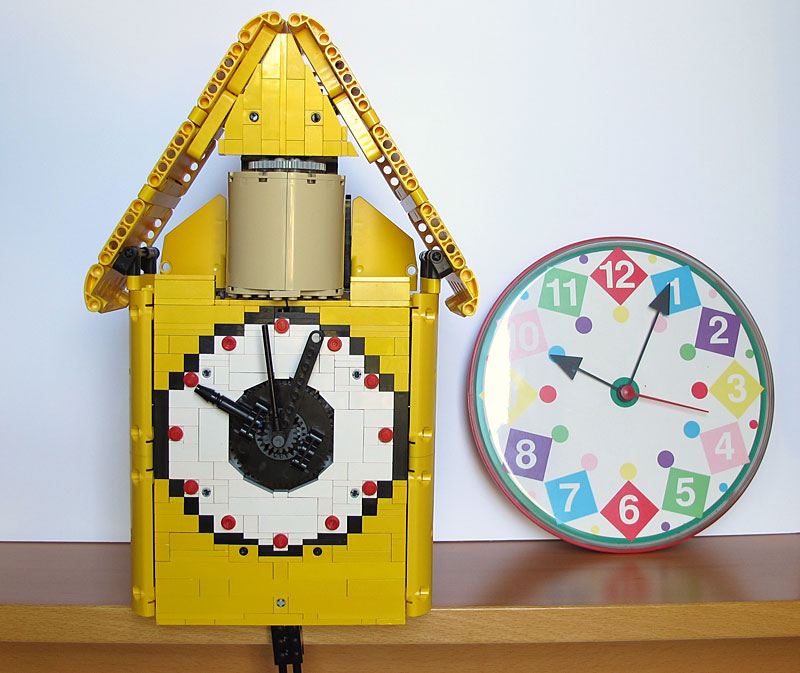
Close-up of the whole clock. |
|
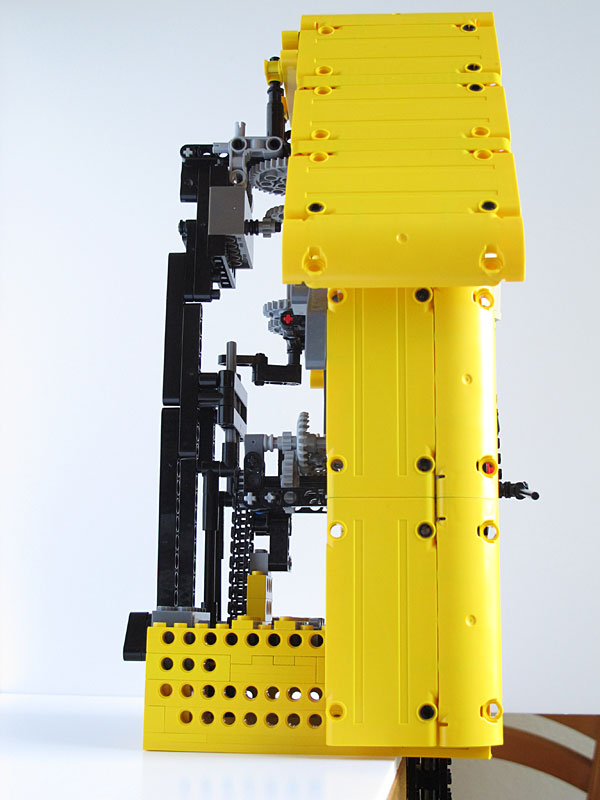
Side view. I didn't have enough panels to completely close the box. The good point is that it shows the mechanisms! |
|
Near reference clock. As you can see on the first video, cuckoo clock speed closely matches real clock one. |
Construction details
|
The first choice I had to do was to select the power source of the clock. Using weight is a classical method, but I like a lot the small wind-up motors 42073, and ended up using two of them, one for the clock itself, the second one to power the cuckoo. |
|
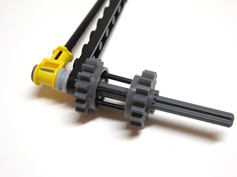
But I was not yet sure this little motor could power the clock long enough. I quickly assembled it on a W4.3 de Ben Van De Waal escapement, and easily got a 2 minutes running time, with direct connection of motor output to escapement. As the motor had power to spare, I multiplied by three the motor output (24t:8t) and obtained 6 minutes running time. It would probably be possible to go further in multiplication to get a longer working time... |
|
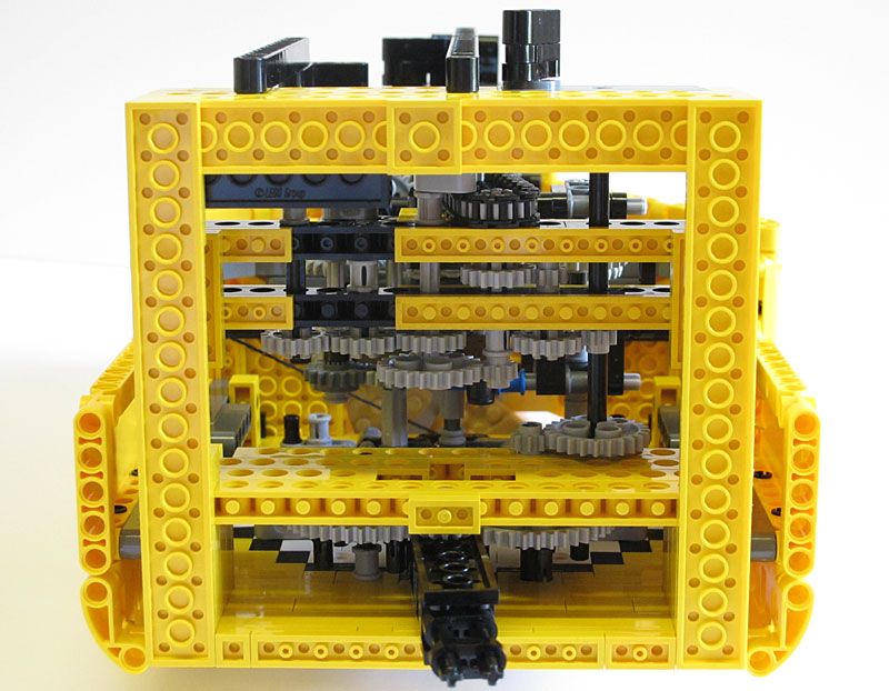
As the Ben Van De Waal's escapement worked fine, was simple, compact and easy to integrate, I used it for my clock. The test structure, a bit improved, became the clock chassis, as can be seen on this bottom view photo. |
|
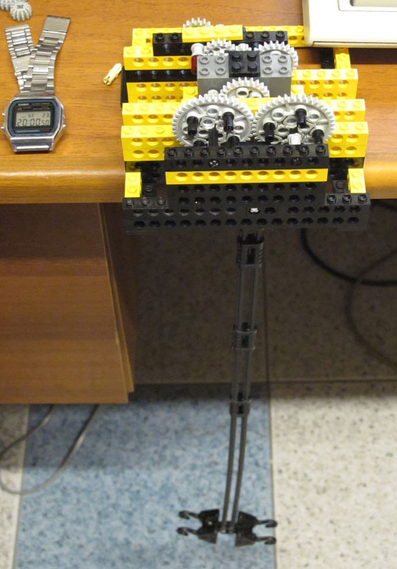
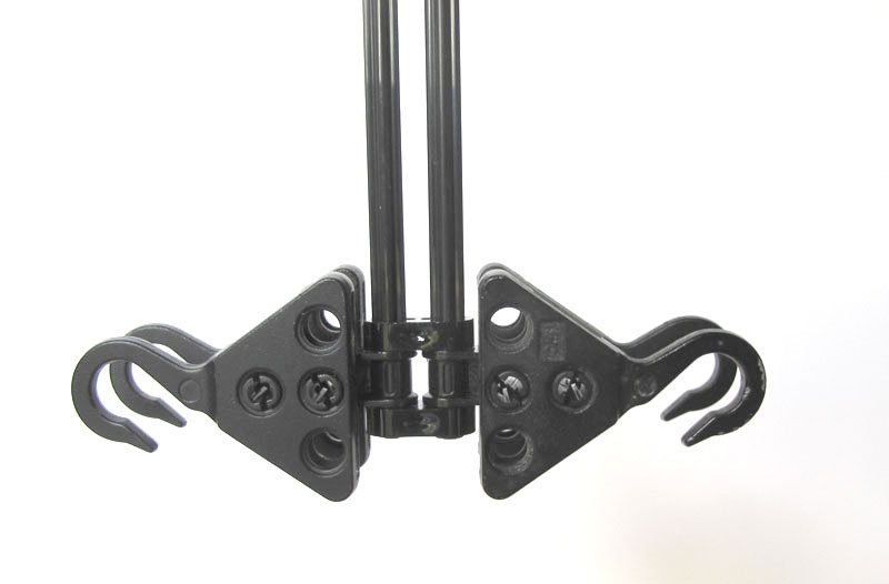
The pendulum itself is built from long Technic axles and 4 metal crane hooks as weight. I find it looked nice... The weight can be easily slid up and down to trim pendulum period. |
|
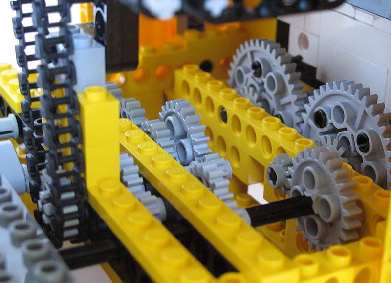
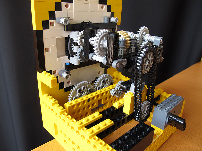
The escapement makes one turn every 4 pendulum periods, that is to say every 5 seconds (8 x 0.625s). This means that I needed to divide by twelve to drive seconds hand. Since the motor output is multiplied by 3 to drive the escapement, taking directly the motor output it only remained to divide by 4. This was done with two 8t:16t gears. The divided output is provided to the dial driver module with a chain. |
|
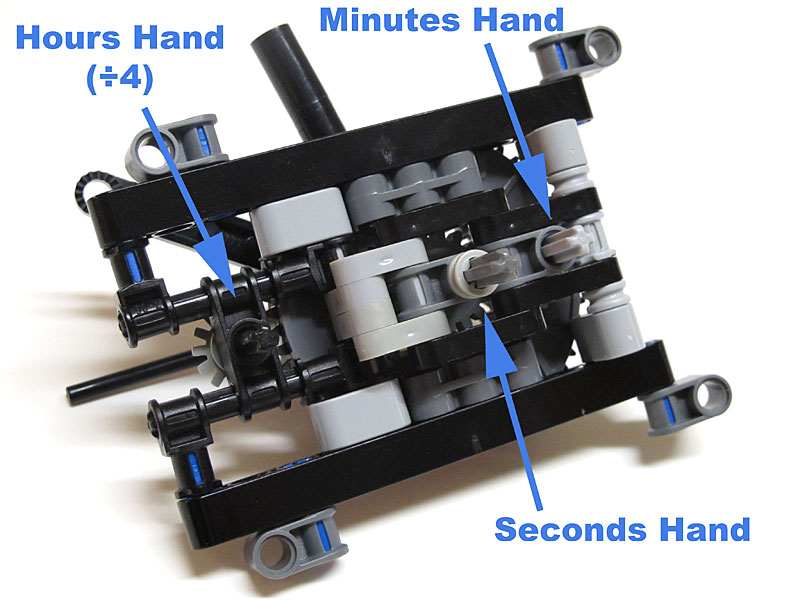
The next module I built is the dial that features three concentric hands. Seconds hand is directly driven by central axle, while hours hand is mounted on the crown of a turntable. |
|
Minutes hand is driven by two head to head 6542 gears, assembled with four 4593 control sticks. It's a bit tricky to assemble, and transmitted torque is not outstanding (though stronger than I first expected). But it allows to directly use a Technic plate as minutes hand, and total handle stack height is just 3 studs. |
|
Backside of the dial module. Hours input is divided by 4 (14t:56t), the dial driver module will only do a simple divide by 3 between minutes and hours. |
|
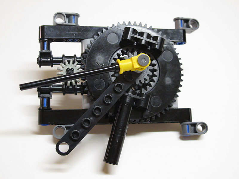
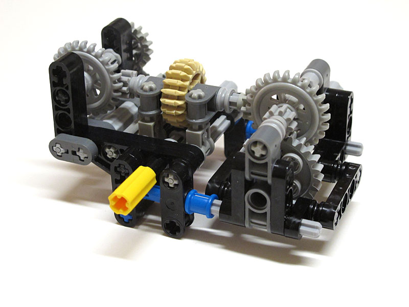
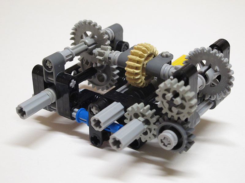
The next module I built was the dial driver module, ensuring proper divisions between hours, minutes and seconds. |
|
Since the needed transmitted torque is fairly low, I used twice a floating assembly on axles to get non-standard spacing. This allowed to use a worm screw on a 20t gear (followed by 8t:24t) to get the proper divide by sixty between seconds and minutes. This setup is very compact. Non-standard spacing was used also to compensate for the odd distance caused by the use of 14t gear for hours in the dial. |
|
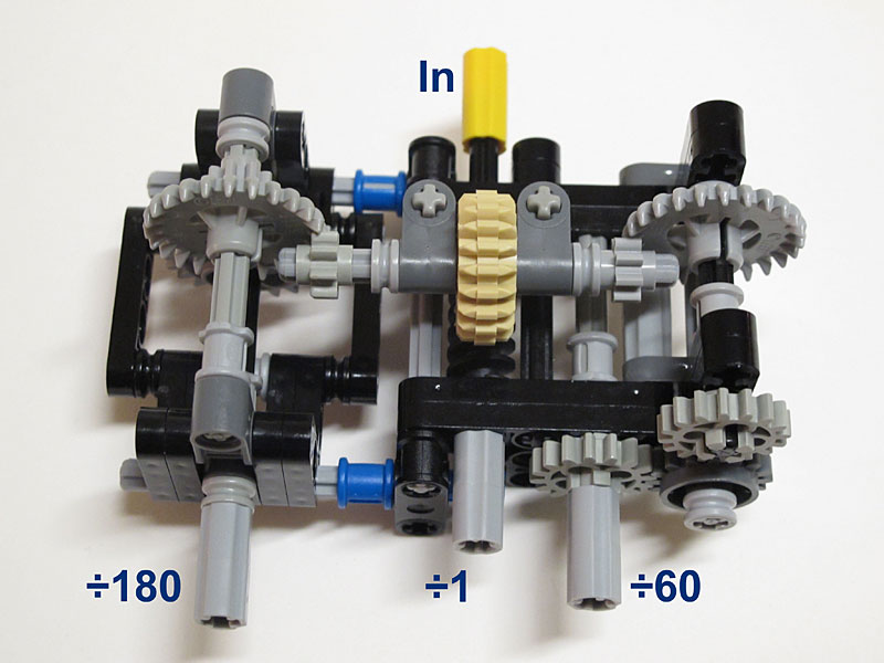
Driver module, showing division ratio. |
|
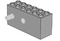
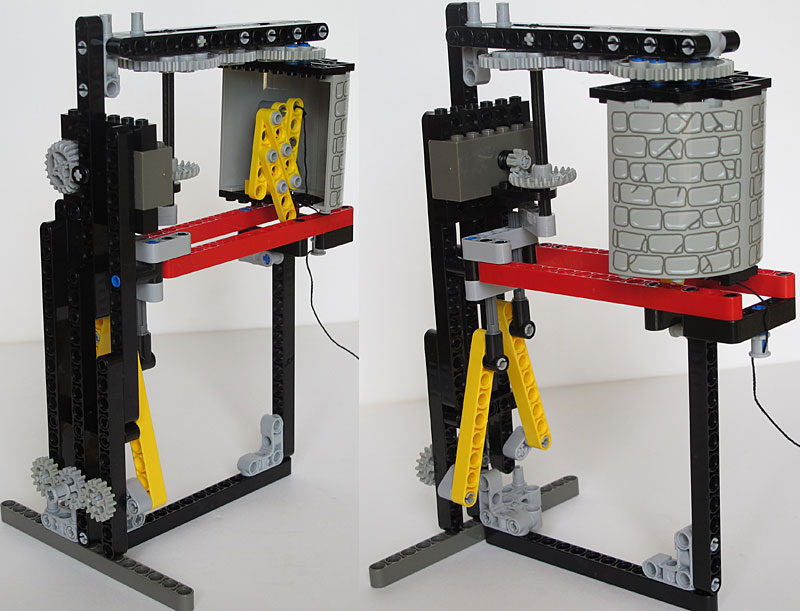
The next step before building the cuckoo mechanism was to assemble all these modules and check the result. It's also at this step that I added a reasonably nice dial background. Noteworthy is the weight brick that is supposed to prevent clock tipping. "Supposed to" because I drop the clock twice during video shooting! |
|
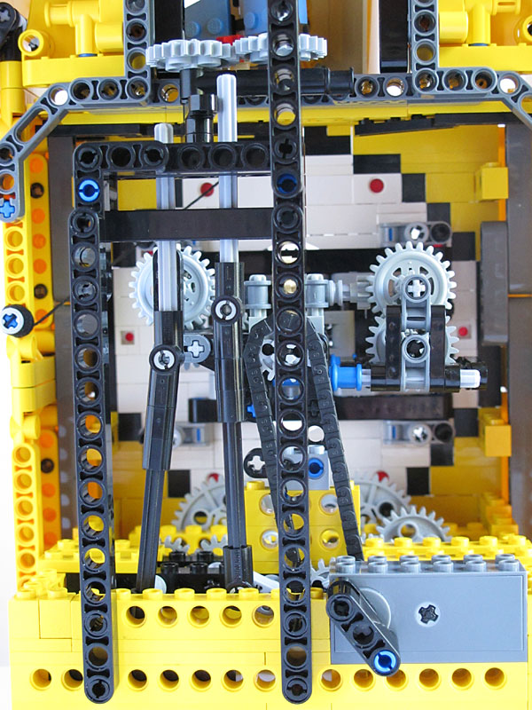
Here is the prototype of the cuckoo. The wind-up motor drives the half cylinder that hides the cuckoo in rest position. When the cuckoo is triggered, the cylinder turns and shows the cuckoo, while a thread gets taught and pulls the lever of scissors mechanism that raises and pulls out the cuckoo. The weight of the cuckoo allows it to go back inside cylinder footprint as soon as the thread is loosen. A double bar interlock mechanism allows to block the rotation and to release the cuckoo only once per cycle. The axles easily slide on the cuckoo lever, so the clock mechanism is not hampered by friction. |
|
Cuckoo! cuckoo! While this mechanism worked quite well, the motor is missing a bit of torque, sometimes failing to lift the cuckoo. I guess I should have used more down gearing on motor output (1:3 here). The other drawback is that as the cuckoo turns, the thread gets more and more twisted, slightly shortening. So you have to adjust its length from time to time... |
|
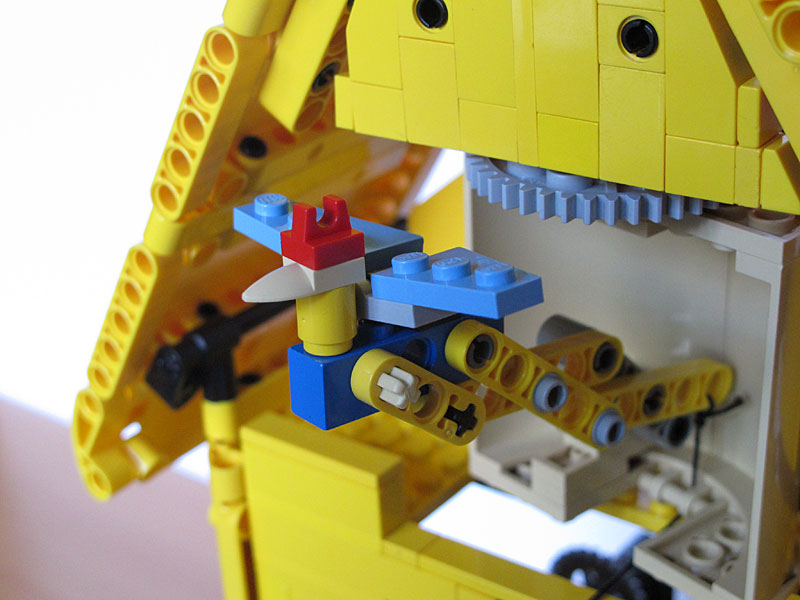
It only remained to add cuckoo mechanism to the clock, and cover it with a few panels. This photo shows the cuckoo release mechanism after integration. On the left you can also see the thread bobbin, used to adjust the tension. |
|
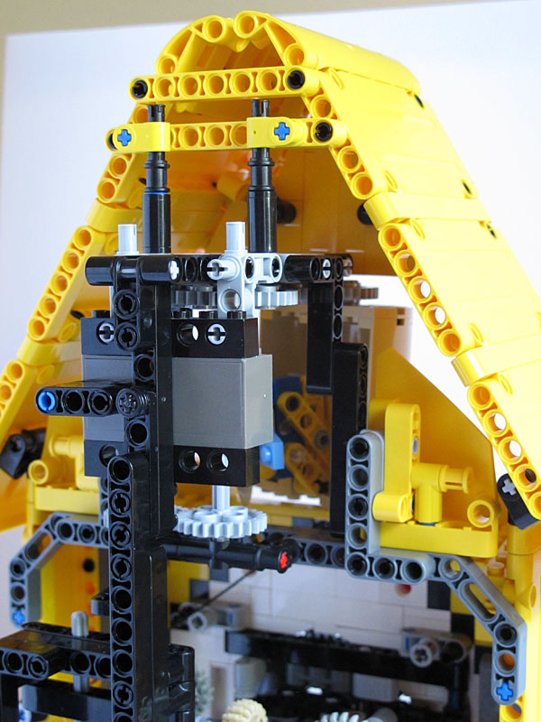
The wind-up motor driving the cuckoo. We can see this one folded down in the back. |
|
Complete view of the back of the clock. |

![]()
![]()
![]()
![]()
![]()
![]()
![]()
![]()
![]()
![]()
![]()
![]()
![]()
![]()
![]()